


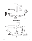

Relief Valve and Flow Sensor Manifold
310645H 25
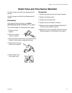
Relief Valve and Flow Sensor Manifold
For 120 V sprayer use Relief Valve Replacement Kit
287325.
For 230 V sprayer use Relief Valve Replacement Kit
287350.
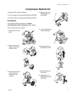
Disassembly
First read and follow instructions in the Before
performing any service on sprayer section, page 9.
Then remove hopper, front and back covers, page 9.
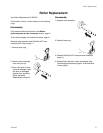
1 Remove air line to
regulator.
2 Remove air line from
cooler to manifold.
3 Disconnect wires to Relief Valve. Pay attention to their
location to insure they are reattached correctly.
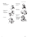
4 Remove 2 nuts securing
Relief Valve to sprayer.
5 Remove Relief Valve
from sprayer frame.
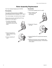
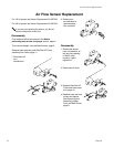
Reassembly
1 Position new relief valve from Kit in back of sprayer.
2 Replace and tighten screws.
3 Reattach wires to Relief Valve.
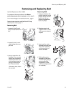
4 Reattach air line from cooler to manifold.
5 Reattach air line to regulator.Replace RotoFlex HD
Pump and hose extension, page 12.
6 Replace front cover and hopper. See Removing and
Replacing Hopper, Front and Back Cover, page 9.
ti4423a
ti4418a
ti4419a