H.E.R.O. INDUSTRIES 1100C & 1100NC OWNERS MANUAL
24
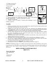
internal circlip groove of piston using circlip pliers.
NOTE: Circlip must fully expand into groove of piston. Circlip has fully expanded when there is
13/64" space between circlip eyelets.
NOTE: If you experience difficulty installing circlip, remove
a small quantity of grease. When
installed correctly, rod should move slowly and without any free play.
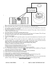
13. If piston seals, (ref# 87) are required, they may be installed now or after piston has been re-attached.
14. Thread rod into eccentric bearing holder, (ref# 95) until nut is flush with eccentric bearing. Tighten
snugly.
NOTE: Piston rod nut must remain fully threaded onto rod, if during installation, the nut begins to
loosen from rod, re-tighten to rod. Place vise grips on rod to assist in tightening piston rod into
eccentric.
15. Remove and discard old piston seals.
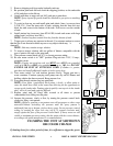
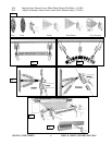
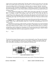
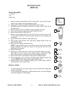
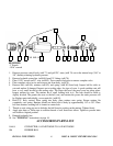
16. Piston seal kits, (ref# 87) contain a total of four pieces (1 o-ring, 1 flat washer, 2 cup washers). Take
note of their installation sequence by referring to drawing. The piston has three machined grooves,
which have been marked on the drawing as A, B, & C.
17. Place flat washer (one side has a contoured face) into groove "C", then place o-ring in front of flat
washer, so that it fits into the contoured face of the flat washer.
18. Place one cup washer into groove "B", with open face of cup washer facing the end of piston. (towards
hydraulic oil when installed)
19. Place second cup washer into groove "A".
NOTE: Always work from the front of the piston back so that
you are always moving the cup
washers over filled grooves. This avoids damage that can occur to the cup washers if they have to be
dug out of one groove and moved to another. Avoid over stretching.
NOTE: A small, dental like tool, may be used to assist in moving cup washers.
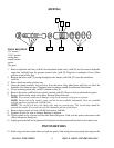
20. Apply grease to seals before installing in cylinder, (ref# 53).
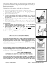
21. Slide pump assembly into side frames and guide piston into cylinder.
NOTE: Use care not to push the piston too far into cylinder. If piston rings slide in too far they will
pass through cylinder into the hydraulic cavity. Complete dismantling of piston will be required to
remove. The piston can not be pulled back if the seals have gone through cylinder.
22. Reattach crossblock bolts, as removed in step 2. Torque bolts to 30 foot pounds.
23. Reconnect hydraulic lines, as removed in step 1.
24. Add new hydraulic oil to hydraulic tank, using only genuine H.E.R.O. LVO hydraulic oil.
25. Once the repairs have been completed, the hydraulic oil will require purging to remove the trapped air.
See "PURGING" instructions on page 16.
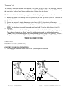
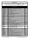
PRESSURE CONTROL VALVE
(REF# 70)