


2 308983
Installation
Pressure Relief Procedure
WARNING
PRESSURIZED EQUIPMENT HAZARD
The equipment stays pressurized until pressure is
manually relieved. To reduce the risk of serious
injury from pressurized fluid, accidental spray, or
splashing fluid, follow this procedure whenever you
D Are instructed to relieve pressure
D Stop pumping
D Check, clean, or service any system equipment
D Install or clean fluid nozzles
1. Shut off the air to the pump.
2. Open the dispensing valve, if used.
3. Open the fluid drain valve to relieve all fluid
pressure, and have a container ready to catch the
drainage.
Removing the Existing Air Motor
1.
Follow the Pressure Relief
Procedure above.
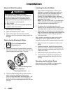
2. Remove the outlet and inlet manifolds, grounding
strip, and vee clamps. Remove the center housing
(shown below) from your Husky 715 pump.
fluid-side diaphragm plate
diaphragm shaft screw
diaphragm
9091A
3. From the center housing that you took off of the
pump, remove the diaphragm shaft screws,
fluid-side diaphragm plates, and diaphragms. You
will re-use these. Do not re-use the diaphragm
shaft or the air-side diaphragm plates with the new
air motor.
Installing the New Air Motor
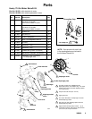
1. Apply medium-strength (blue) LoctiteR (9) or
equivalent to threads of diaphragm shaft screw.
Install on one end of the diaphragm shaft the
following parts (see proper order in Parts
Drawing): air-side diaphragm plate, diaphragm,
fluid-side diaphragm plate, packing o-ring (7), and
diaphragm shaft screw.
NOTE: The words “AIR SIDE” on the diaphragm
and the flat side of the air-side diaphragm plate
must face toward the diaphragm shaft.
2. Put grease (8) on the diaphragm shaft, and
carefully (do not damage the shaft u-cups) run the
diaphragm shaft through the center housing bore.
3. Repeat step 1 for the other end of the diaphragm
shaft, and torque the diaphragm shaft screws to 80
to 90 in-lb (9 to 10 N-m) at 100 rpm maximum.
4. Install the muffler.
When installing vee clamps in step 6, orient center
housing so air inlet is approximately 45_ above
horizontal and the muffler is approximately horizontal.
5. Apply thin, even film of grease on inside of vee
clamp.
6. Position fluid covers, install vee clamps around
fluid and air covers, install grounding strip on vee
clamps, and torque vee clamp nuts from 80 to 90
in-lb (9 to 10 N-m).
7. Make sure all check valve parts are in place.
8. Install manifold o-rings (6) and manifolds, and
torque manifold bolts from 80 to 90 in-lb (9 to
10 N-m).
Operating the Retrofitted Pump
See instruction manual 308981 for Operating and
Service instructions and Parts information.