


3093796
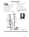
Hydraulic Pump
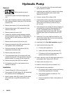
Removal
1.
Relieve pressure; page 4.
Let hydraulic system cool before beginning ser-
vice.
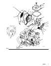
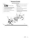
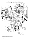
2. Fig 2. Use 3.5 gallon container to catch hydraulic
fluid. Remove reservoir drain plug (133) and drain
hydraulic fluid.
3. Remove two screws (141) and fan shroud (23).
4. Remove eight screws (136), washers (81) and
reservoir cover (50).
5. Remove cooler clip screw (141).
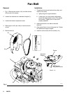
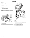
6. Loosen four engine mounting fasteners and belt
tension adjustment screw (Fig. 3). Slide engine to
left (rear view) to relieve tension on belt (6). Re-
move belt.
7. Remove two set screws (18) and fan (19).
8. Disconnect hydraulic tube (52) from elbow (54)
and hydraulic motor manifold (46).
9. Disconnect strainer (25) with elbows (58, 30)
assembled, from elbow (139).
10. Remove case drain tube (67).
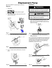
11. Turn compensator stem (A) clockwise until stop.
Loosen set screw (B). Pull compensator stem out.
Remove holder (C), spring (D) and coupler (E).
12. Remove two pump bolts (94) from reservoir.
13. Lift hydraulic pump (2) up and toward front of
reservoir to remove.
Installation
1. Transfer fittings (53, 139) to new pump (2).
2. Place strainer (25) with fittings (30, 58) assembled,
into reservoir prior to installing pump.
3. Attach hydraulic tube (52) to pump (2) with elbow
(53). Install new o-ring (56) on hydraulic pump
flange
4. Fig 2. Set hydraulic pump (2) down and toward
rear of reservoir to install.
5. Install two pump bolts (94) in reservoir with copper
washers (64) on outside under screw heads.
Torque to 31–35 ft-lb.
6. Connect strainer (25) to elbow (139).
7. Connect elbow (54) to hydraulic motor manifold
(46). Connect hydraulic tube (52) to elbow (54).
Torque hex nuts on elbows (139) and (53) to
38 – 42 ft-lb.
8. Insert spring (D) into coupler (E) and put holder (C)
on exposed end of spring. Slide assembly (D, E,
C) over compensator stem (A). Align flat on
compensator stem with set screw (B). Hold com-
pensator stem knob and torque set screw to 90
in-lb.
9. Install key (F) on pump shaft and install fan (19)
with two set screws (18). Fan hub must overhang
shaft approximately 0.20 in.
10. Install belt (6). Do Fan Belt Installation, page 8.
11. Install reservoir drain plug (133).
a. Fill pump with hydraulic oil.
b. Install case drain elbow (24) and tube (67).
c. Fill reservoir to fill level (approximately 2.75
gallons) with Graco hydraulic fluid.
12. Install reservoir cover (50) with eight washers (81)
and screws (136). Torque to 95–100 in-lb.
13. Install cooler clip screw (141).
14. Install fan shroud (23) with two screws (141).
15. Verify hydraulic pump operation:
a. Run sprayer with hydraulic motor slow stroking
and minimum pressure for 2 minutes.
b. Set hydraulic pressure at maximum. Turn
pump switch OFF.
c. Check for hydraulic oil leaks. Add hydraulic oil
as needed.