


English
6
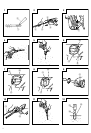
5. Bolt placing operation with Chemical Anchor.
(Rotation + Hammering)
6. Crushing (Hammering)
7. Groove digging and edging (Hammering)
8. Asphalt cutting (Hammering)
9. Scooping Work (Hammering)
10.Surface Roughing (Hammering)
11.Tamping (Hammering)
12.Syringe (for chip removal)
⅜ Hammer grease A
500 g (in a can)
70 g (in a green tube)
30 g (in a green tube)
Optional accessories are subject to change without
notice.
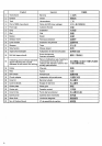
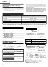
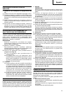
APPLICATIONS
⅜ Drilling holes in concrete
⅜ Drilling anchor holes
(Standard socket
on the market)
(SDS max shank)
12.7 mm Chemical
Anchor Adaptor
19 mm Chemical
Anchor Adaptor
(1) Bull point
Overall length: 280, 400 mm
(1) Cold chisel
Overall length: 280, 400 mm
(1) Cutter
(1) Scoop
(2) Shank
(1) Bushing Tool
(2) Shank
(1) Rammer
150 × 150 mm
⅜ Crushing concrete, chipping, digging, and squaring
(by applying optional accessories)
PRIOR TO OPERATION
1. Power source
Ensure that the power source to be utilized conforms
to the power requirements specified on the product
nameplate.
2. Power switch
Ensure that the power switch is in the OFF position.
If the plug is connected to a power receptacle while
the power switch is in the ON position, the power
tool will start operating immediately, which could
cause a serious accident.
3. Extension cord
When the work area is removed from the power
source, use an extension cord of sufficient thickness
and rated capacity. The extension cord should be kept
as short as practicable.
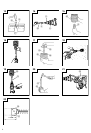
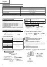
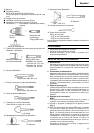
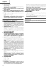
4. How to install tool
NOTE
For tools such as a bull point and a cold chisel, use
only Hitachi genuine parts.
(1) Clean, then smear the tool shank with the grease
provided in the green tube (Fig. 1).
(2) To attach the tool (SDS max shank), insert it into the
hole until it contacts the innermost end of the hole as
illustrated in Fig. 2.
If you continue to turn the tool with slight pressure,
you can feel a spot where there is a hitch. At that
spot, pull the grip to the direction of an arrow mark
and insert the tool all the way until it hits the innermost
end.
Releasing the grip reverts the grip and secures the
tool in place.
(3) Pull the tool to make sure it is locked completely.
(4) To remove the tool, fully pull the grip in the direction
of the arrow and pull out the tool.
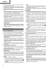
5. Regulating the number of rotations and hammering
(Fig. 3)
This Rotary Hammer is equipped with a built-in
electronic control circuit that can adjust and regulate
the number of rotations and times of hammering. This
Rotary Hammer can be used by adjusting the dial,
depending upon the contents of operation, such as
boring holes into fragile materials, chipping,
centering, etc.
The scale ‘1’ of the dial is designed for a minimum
speed with the number of 240 rotations per minute
and 1320 times of blow per minute. The scale ‘6’ is
designed for a maximum speed with the number of
480 rotations per minute and 2650 times of blow per
minute.
CAUTION:
Do not adjust the dial during operation. Doing so can
result in injury because the Rotary Hammer must be
held by only one hand, disabling the steady control
of the Rotary Hammer.
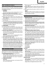
HOW TO USE THE ROTARY HAMMER
1. How to drill holes (Fig. 4)
(1) Pull the switch trigger after applying the drill bit tip to
the drilling position.