


English
13
●
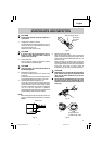
Since the built-in micro computer takes about 3
seconds to confirm that the battery being charged
with UC18YGSL is taken out, wait for a minimum
of 3 seconds before reinserting it to continue
charging. If the battery is reinserted within 3
seconds, the battery may not be properly charged.
BEFORE USE
Check the work area to make sure that it is clear of debris
and clutter.
Clear the area of unnecessary personnel. Ensure that
lighting and ventilation is adequate.
OPERATION
How to make the batteries perform longer
⅜
Recharge the batteries before they become
completely exhausted.
When you feel that the power of the tool becomes
weaker, stop using the tool and recharge its
battery. If you continue to use the tool and exhaust
the electric current, the battery may be damaged
and its life will become shorter.
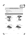
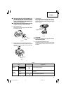
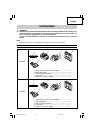
1. Installing the bit
Loosen the sleeve by turning it toward the left (in
the counterclockwise direction as viewed from the
front) to open the clip on the keyless chuck. After
inserting a driver bit, etc., into the keyless drill
chuck, and tighten the sleeve by turning it toward
the right (in the clockwise direction as viewed from
the front). (See Fig. 5)
Fig. 5
⅜
If the sleeve becomes loose during operation,
tighten it further.
The tightening force becomes stronger when the
sleeve is tightened additionally.
2. Removing the bit
Loosen the sleeve by turning it toward the left (in
the counterclockwise direction as viewed from the
front), and then take out the bit ect. (See Fig. 5)
CAUTION
When it is no longer possible to loosen the sleeve,
use a vise or similar instrument to secure the bit.
Set the clutch mode between 1 and 11 and then
turn the sleeve to the loose side (left side) while
operating the clutch. It should be easy now to
loosen the sleeve.
3. Automatic spindle-lock mechanism
This unit has automatic spindle-lock mechanism
for quick bit changes.
4. Confirm that the battery is mounted correctly
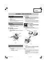
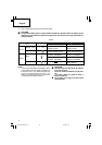
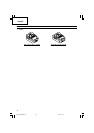
5. Confirm the clutch dial position (See Fig. 6)
The tightening torque of this unit can be adjusted
according to the clutch dial position, at which the
clutch dial is set.
Fig. 6
(1) When using this unit as a screwdriver, line up the
one of the numbers “1, 3, 5 ... 22” on the clutch dial,
or the dots, with the triangle mark on the outer body.
(2) When using this unit as a drill, align the clutch dial
drill mark “ ” with the triangle mark on the outer
body.
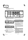
CAUTION
●
The clutch dial cannot be set between the numbers
“1, 3, 5 ... 22” or the dots.
●
Do not use with the clutch dial numeral between
“22” and the line at the middle of the drill mark.
Doing so may cause damage. (See Fig. 7)
Fig. 7
Driver bit
Triangle mark
Drill mark
Weak
Clutch dial
Loosen
Tighten
Strong
Sleeve
Line
Triangle mark
Drill mark
01Eng_DS14DSAL_US 10/7/08, 16:1713