


— 9 —
English
OPERATION AND MAINTENANCE
NOTE:
The information contained in this Instruction Manual is designed to assist you in the safe operation and maintenance of
the compressor.
Some illustrations in this Instruction Manual may show details or attachments that differ from those on your own
compressor.
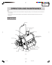
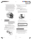
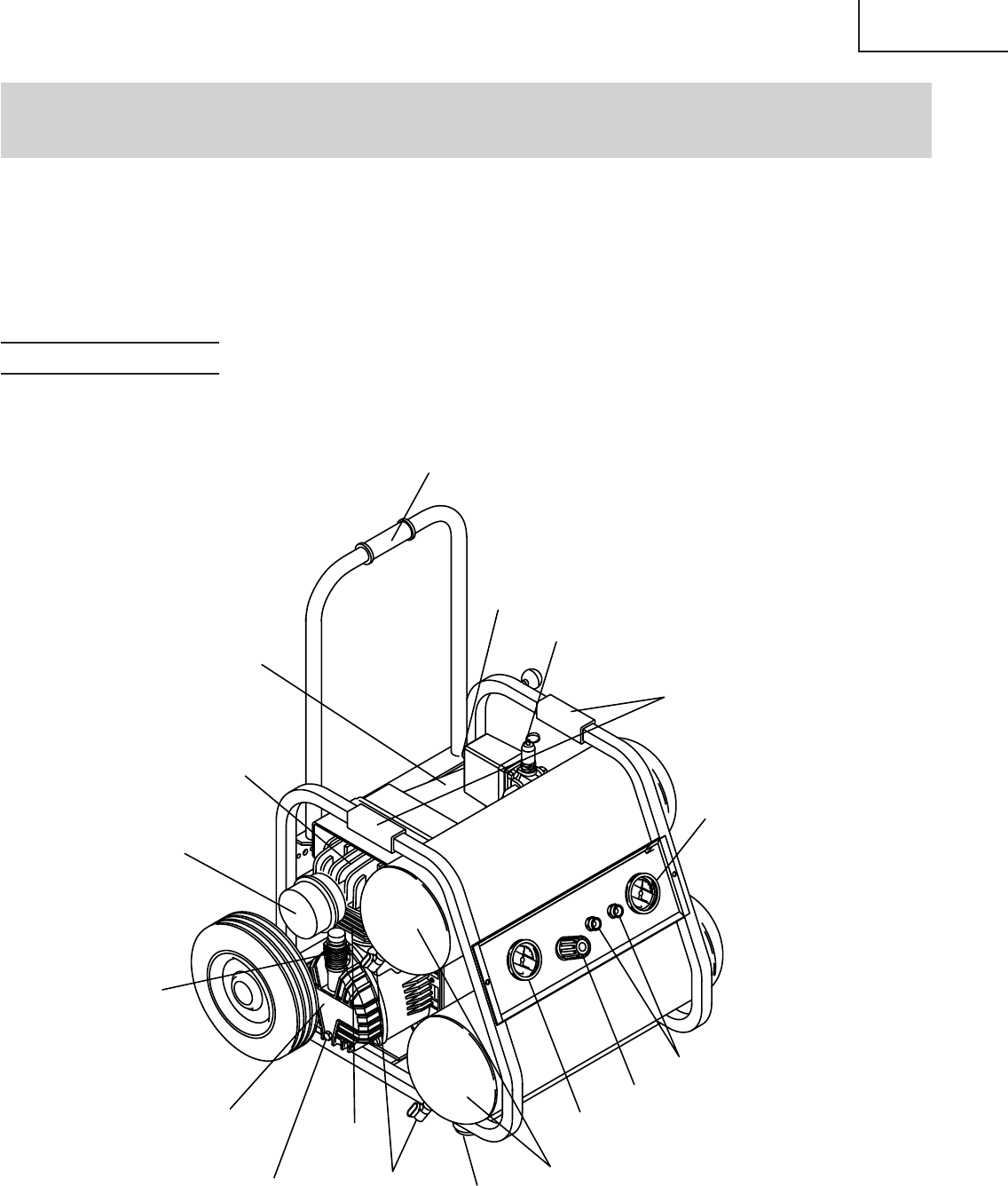
NAME OF PARTS
Fig. 1
Handle (B)
Safety valve
Dipstick
Intake filter
Knob of the pressure reducer
Joint (air outlet)
Drain cock
Knob of the pressure switch
Tank
Casing cover
Drain cap
Cylinder
Pressure gauge (A)
indicates the pressure
in the air tank
Pressure gauge (B)
indicates the working pressure
Motor
Head
Handle (A)
Rubber bumper
e_ec129_e.p65 4/8/04, 5:38 PM9