


- 9 -
B) Remove any moisture in this compressor air tank.
Gradually open the drain cock and discharge the
drain. Close tightly when drained.
C) Make sure the engine switch is in the “OFF”
position.
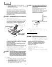
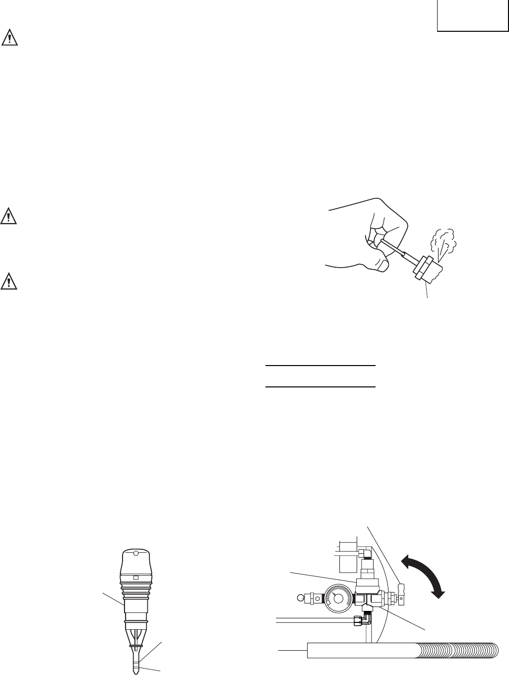
D) Make sure the safety relief valve is working correctly.
(Fig. 3)
The safety relief valve is designed to prevent system
failures by relieving pressure from the system when
this compressed air reaches a predetermined level.
The safety relief valve is preset by the manufacturer
and must not be modified in any way. To verify the
safety relief valve is working properly, pull on the
ring. Air pressure should escape. When the ring is
released, it will reset.
E) Make sure all guards and covers are in place and
securely mounted.
1. Start up
A) Read safety warnings before performing operation.
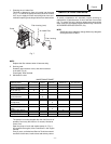
B) When the toggle is in the upright position, all air
from this compressor is vented through the
discharge muffler (Fig. 4). This gives an easy start
feature. For normal operation, the toggle is in the
90° position.
English
WARNING Do not smoke while fueling.
Do not fill fuel tank while this compressor is
running or hot. Allow this compressor and
engine to cool down for two minutes before
refueling.
Do not refuel indoors or in a poorly ventilated
area.
Do not fill fuel tank to point of overflowing.
Always refuel slowly to avoid the possibility of
spilled fuel which may cause a fire.
Do not operate this compressor if gasoline is
spilled. Wipe this compressor clean and move
it away from the spill. Avoid creating any
ignition until the gasolinehas evaporated.
Allow approximately 1/4” of tank space for fuel
expansion.
WARNING Always store fuel away from this compressor
while it is running or hot.
H) Refer to the engine manual for all necessary
maintenance and adjustments.
WARNING Do not operate this compressor in an enclosed
area. Use this compressor only in well
ventilated areas. The exhaustfrom the engine
contains carbon monoxide, a poisonous,
odorless and invisible gas. Breathing the gas
can cause serious injury, illness and possible
death.
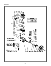
4. Air coupler installation
Screw in the air coupler to the joint of regulator mounting
bracket (Refer to Fig. 1 and Fig. 5). The screw size of the
joint is 3/8”. Use an air coupler which has the same screw
size.
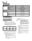
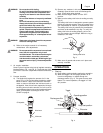
5. Pre-start checklist
A) The dipstick will register the amount of oil in the
pump. (Fig. 2) Oil level should be checked on a daily
basis to ensure it does not exceed the maximum
notch or does not fall below the minimum notch on
the dipstick. If the oil level is low, replenish oil through
the filling hole so that the amount of oil will come to
a point between the maximum notch and the minimum
notch on the dipstick according to the OIL TYPE
CHART on page 8.
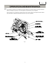
OPERATION
Fig. 2
Fig. 4
Safety relief valve
Oil dipstick
Maximum
Minimum
Fig. 3
Discharge muffler
Toggle
Pilot valve
Operating position
Easy start position