


6
English
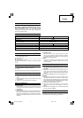
SPECIFICATIONS
Model FCJ65V3 FCJ65S3
Voltage (by areas)* (110V, 115V, 120V, 127V, 220V, 230V, 240V)
Power input 400W*
Wood: 65mm
Max. cutting depth
Mild steel: 6mm
No-load speed 0 – 3000 min
–1
3000
min
–1
Stroke 18mm
Min. cutting radius 25mm
Weight (without cord) 1.5kg
* Be sure to check the nameplate on product as it is subject to change by areas.
STANDARD ACCESSORIES
(1) Blade No.31.................................................................1
For cutting thick lumber
(2) Splinter guard.............................................................1
(3) Chip cover ...................................................................1
(4) Hexagonal bar wrench...............................................1
Standard accessories are subject to change without
notice.
OPTIONAL ACCESSORIES (sold separately)
(1) Blades, No.1 – No.6, 31*
* No.31 Blade is a standard accessory.
(2) Guide
Optional accessories are subject to change without notice.
APPLICATIONS
⅜ Cutting various lumber and pocket cutting
⅜ Cutting mild steel plate, aluminum plate, and copper
plate
⅜ Cutting synthetic resins, such as phenol resin and
vinyl chloride
⅜ Cutting thin and soft construction materials
PRIOR TO OPERATION
1. Power source
Ensure that the power source to be utilized conforms
to the power requirements specified on the product
nameplate.
2. Power switch
Ensure that the power switch is in the OFF position. If
the plug is connected to a receptacle while the power
switch is in the ON position, the power tool will start
operating immediately, which could cause a serious
accident.
3. Extension cord
When the work area is removed from the power
source, use an extension cord of sufficient thickness
and rated capacity. The extension cord should be
kept as short as practicable.
4. RCD
The use of a residual current device with a rated
residual current of 30mA or less at all times is
recommended.
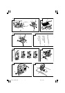
MOUNTING THE BLADE
1. Use the accessory hexagonal bar wrench to loosen
the blade set screws on the blade holder, as shown in
Fig. 1(a).
2. Holding the blade with its cutting edge facing the
front, insert the mounting portion of the blade into
the plunger groove until it touches the bottom of the
groove.
3. As shown in Fig. 1(b), firmly clamp the side screw.
CAUTION
⅜ Loosened set screws may cause the blade to be
damaged. Always ensure that the set screws are
securely tightened. Always ensure that the plunger
groove is clean and clear of sawdust to ensure proper
blade mounting and set screw clamping.
4. Storing the hexagonal bar wrench
(1) Insert in a hole on the side of the main unit with
holding the short side horizontally as shown in
Fig. 2.
(2) Rotate with the hexagonal bar wrench inserted and
secure as shown in Fig. 2.
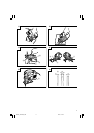
ADJUSTING THE GUIDE ROLLER
The guide roller, shown in Fig. 3, is employed to prevent
the blade from snapping. Prior to use, adjust guide roller
in accordance with the following procedures:
PRECAUTIONS ON USING JIG SAW
Hold power tool by insulated gripping surfaces, when
performing an operation where the cutting accessory
may contact hidden wiring or its own cord. Cutting
accessory contacting a "live" wire may make exposed
metal parts of the power tool "live" and could give the
operator an electric shock.
01Eng_FCJ65V3_WE 4/8/11, 10:526