


7
EnglishEnglish
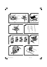
(1) Loosen the holder set screw with the accessory
hexagonal bar wrench.
(2) Gently slide the guide roller until the roller groove
lightly touches the back of the blade.
NOTE
On delivery from the factory, there is a gap of about
3mm between the roller and blade.
(3) Firmly tighten the holder set screw.
CAUTION
⅜ The guide roller can be used only for Blades that
have a straight line on the rear that is longer than
50mm. (Fig. 4A and 4B) When using other types
of blades (Fig. 4C), slide the guide roller in
backwards so that the guide roller does not contact
the blade.
⅜ When cutting thick boards or performing
continuous cutting operations, use the blade
shown in the Fig. 4A, 4B and be sure to set the
guide roller.
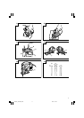
CHIP COVER POSITIONING
1. Chip cover
Use the chip cover to reduce flying of cut particles
and to easily operate the saw.
Slide the chip cover while lightly pressing its front
section.
The chip cover can be set at three positions as shown
in Fig. 5.
2. How to choose the position of the ship cover
Set the chip cover to the first step when attaching or
removing the blade.
Set the chip cover to the second step when cutting
wooden materials.
Set the chip cover to the second or third step when
cutting metal materials such as steel.
CAUTION
⅜ Keep always the chip cover in the low position when
operating the tool.
⅜ Wear protection glasses even if the chip cover is
used.
ADJUSTING THE BLADE OPERATING
SPEED ...........................................(FCJ65V3 only)
NOTE
The blade operating speed cannot be adjusted for
FCJ65S3.
The blade operating speed can be adjusted within a
range of 0 to 3,000 min
–1
according to the degree that the
trigger switch is depressed. Select the speed appropriate
to the material being worked and/or the working
conditions.
To achieve continuous operation, pull the trigger switch
all the way back and depress the stopper. Then, turn the
speed adjustment knob to adjust the blade operating
speed as desired.
NOTE
The speed adjustment knob rotates approximately 1.5
turns. To turn the switch OFF, pull the trigger switch
again to disengage the stopper, and release the trigger
switch.
CUTTING
CAUTION
⅜ While sawing, the base must be firmly in contact with
the material surface, and the blade must be held at a
right angle. If the base becomes separated from the
material, it could cause the blade to break.
⅜ When cutting while holding the front surface, be
careful of the moving blade and hold the upper part
firmly.
1. Rectilinear cutting
(1) To ensure accurate rectilinear cutting, employ the
optional accessory guide as shown in Fig. 6.
(2) Use the splinter guard to reduce roughness of the
cutting surface of wooden materials. Attach the
splinter guard by inserting it from the front section of
the base until it clicks into place. (Fig. 7)
CAUTION
Set the base in the front position when using the
splinter guard.
2. Cutting a circle or a circular arc
To ensure efficient cutting, employ the optional
accessory guide and nail or wood screw as shown in
Fig. 8.
When mounting the guide, loosen the base bottom
screw, and shift the base as far forward as it will go.
3. Sawing curved lines
When sawing a small circular arc, reduce the feeding
speed of the machine. If the machine is fed too fast, it
could cause the blade to break.
4. Cutting metallic materials
Always use an appropriate cutting agent (spindle oil,
soapy water, etc.). When a liquid cutting agent is not
available, apply grease to the back surface of the
material to be cut.
5. Pocket cutting
(1) In lumber
Aligning the blade direction with the grain of the
wood, cut step by step until a window hole is cut in
the center of the lumber. (Fig. 9)
(2) In other materials
When cutting a window hole in materials other than
lumber, initially bore a hole with a drill or similar tool
from which to start cutting.
6. Angular cutting
Set the chip cover to the first step. (Fig. 5)
To adjust the angle of inclination; loosen the base
bottom screw, shift the base position to the side
groove of the semicircular portion, align the scale on
the base semicircular portion (figures engraved on
the scale indicate the angle of inclination) with the
housing edge line, and thoroughly tighten the base
bottom screw. (Fig. 10 and 11)
CAUTION
Set the screw to the opposite side of the inclining
side when using the guide. (Fig. 12)
7. Dust produced in operation
CAUTION
⅜ To prevent accidents, turn the switch off and remove
the plug from the power supply when not in use.
⅜ For instruction on using the dust collector and
applicable cutting debris, please read the dust
collector instruction manual.
01Eng_FCJ65V3_WE 4/8/11, 10:527