


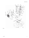
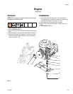
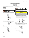
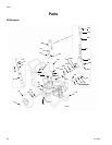
Displacement Pump
311797F 17
Displacement Pump
GH130 Only
(Figures 7-12)
See manual 311845 for pump repair instructions
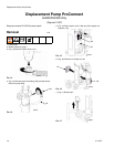
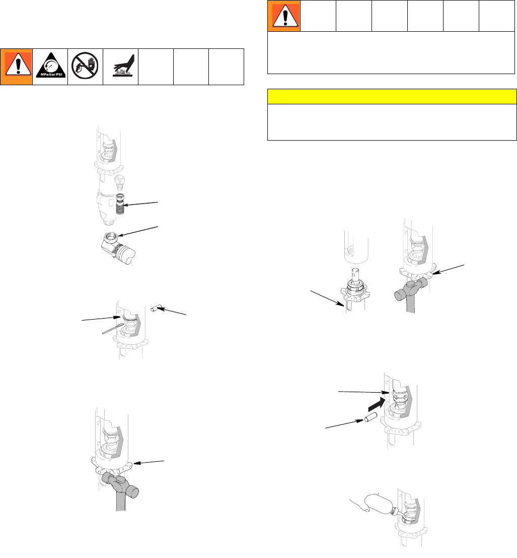
Removal
1. Flush pump.
2. Relieve pressure, page 7.
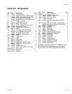
3. (Fig. 7) Remove suction tube (114) and paint hose (63)
(remove at swivel end).
FIG. 7
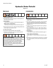
4. (Fig. 8) Push retaining ring (120) up; push out pin (92).
FIG. 8
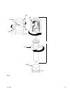
5. (Fig. 9). Loosen jam nut (86). Unscrew pump (111).
FIG. 9
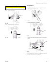
Installation
1. (Fig 10) Screw jam nut (86) to bottom of pump (111)
threads. Screw pump (111) completely into manifold.
Unscrew pump (111) from manifold until pump outlet
aligns with hose. Hand tighten jam nut (86), then tap 1/8
to 1/4 turn with hammer or torque to 75 ft-lb (101 N·m).
FIG. 10
2. (Fig. 11) Slowly pull engine starter rope until pump rod pin
hole is aligned with hydraulic rod hole. Fig. 8. Push pin (92)
into hole. Push retaining ring (120) into groove.
FIG. 11
3. (Fig. 12) Fill packing nut with Graco TSL.
FIG. 12
ti2272a
114
63
TIB
92
120
ti2272c
86
If pin (92) works loose, parts could break off and project
through the air, resulting in serious injury or property dam-
age. Make sure pin is properly installed.
CAUTION
If the pump jam nut (86) loosens during operation, the
threads of the bearing housing and drive train will be dam-
aged. Tighten jam nut (86) as specified.
ti2272d
86
111
TIE
120
92
ti2272f