


7
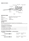
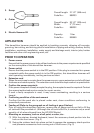
3. Scoop
Overall length: 21-1/2” (546 mm)
Code No.: 985233
4. Cutter
Overall length: 20-1/2” (520 mm)
Width: 3” (75 mm)
Code No.: 985232
5. Electric Hammer Oil
Capacity: 1 liter
Code No.: 955009
APPLICATION
This demolition hammer should be applied to breaking concrete, chipping off concrete,
grooving, bar cutting, and driving piles in installation of piping and wiring, sanitary facility
installation, machinery installation, water supply and drainage work, interior jobs, harbor
facilities and other civil engineering work, etc.
PRIOR TO OPERATION
1. Power source
Ensure that the power source to be utilized conforms to the power requirements specified
on the name plate of this demolition hammer.
2. Power switch
Ensure that the power switch is in the OFF position. If the plug is connected to a power
receptacle while the power switch is in the ON position, this demolition hammer will
start operating immediately, inviting serious accident.
3. Extension cord
When the work area is remote from the power source, use an extension cord of sufficient
thickness and rated capacity. The extension cord should be kept as short as practicable.
4. Confirm the power receptacle
If the power receptacle loosely accepts the plug, the receptacle must be repaired. Contact
the nearest authorized service center for repair service.
If such a faulty receptacle is used, it may cause overheating, resulting in a serious
hazard.
5. Confirming condition of the environment
Confirm that the work site is placed under neat, clean conditions conforming to
prescribed precautions.
6. Feeding oil (Refer to the paragraph on oil feeding at page 9 below.)
Prior to using this demolition hammer, remove the oil gauge and do not fail to fill the
oil tank with the provided oil. (Although the oil tank is built in, it contains only a small
quantity of oil when shipped from the HITACHI Works.)
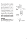
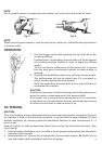
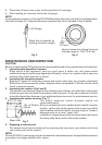
7. Mounting an accessory, such as a bull point, a cutter, etc..
(1) With the retainer directed backward, insert the accessory shank portion into the
hole on the front cover. (Fig. 2)
(2) Swing the retainer back into place so that it engages the accessory shank portion
and prevents accessories from coming out of front cover. (Fig. 3)