


4-1
4. The check of control power supply voltage and a control signal
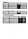
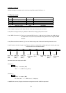
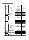
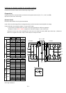
4.1 Control power supply
Measurement place
Item
Tolerance level
+ -
PV5 +5V power supply
4.5V - 5.5V J1 connector 25,16pin Control terminal L
PV12 +12V power supply
10.8V - 13.2V J1 connector 7pin Control terminal L
NV12 -12V power supply -13.2V - -10.8V J1 connector 5pin Control terminal L
PV24 24V power supply
21.6V - 26.4V
J1 connector 3,4pin,
Control terminal P24
Control terminal CM1
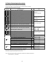
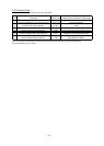
4.2 Control signal
Signal Measurement place The contents of operation Observation waveform
VDC J1 connector 12pin-L
A main circuit direct-current voltage
detected signal
VDC=6.396V/400V*VPN(200Vclass)
VDC=6.396V/800V*VPN(400Vclass)
Direct-current voltage
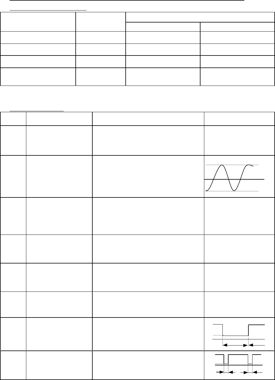
IUF
IWF
J1 connector 9pin-L
J1 connector 8pin-L
A motor current detected signal
At the time of inverter rated load: About
3.3 V peak
TRIP J1 connector 21pin-L
The signal at the time of carrying out a
trip by the trip factor which a gate array
judges (P3-1 reference)
Normal : 5V(H)
Inside of a trip : about 0.3V(L)
Direct-current voltage
PHF J1 connector 22pin-L
Phase failure protection detected
signal
Normal :5V(H)
Phase failure detection :about0.5V(L)
Direct-current voltage
IPL J1 connector 11pin-L
The instantaneous power failure signal
of R0-T0 part
Power On : about0.5V(L)
Power Off : 5V(H)
Direct-current voltage
GS J1 connector 20pin-L
Power-module protection
Under operation : about 5V(H)
Under a stop : about 0.5V(L)
Direct-current voltage
US
VS
WS
J1 connector 17pin-L
J1 connector 18pin-L
J1 connector 19pin-L
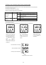
PWM signal
Upper arm ON : about 3.5V(L)
lower arm ON : about 5V(H)
GS J1 connector 30pin-L
The trip distinguished by GA is canceled.
Normal : about 5V(H)
Under reset : about 0.5V(L)
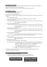
0V
-3.3V
3.3V
3.5V
5V
0V
Upper arm ON
Lower arm ON
Reset Reset
5V
0.5V
0V