


5
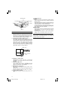
(2) After ensuring that the sanding pad is free of dust
and oil, mount the sanding paper to the sanding
pad as shown in Fig. 2, ensuring that the outer
circumferences of the pad and paper are matched.
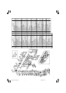
(3) Ensure that the sanding paper is securely attached
to the pad by pressing the paper strongly with the
palm of the hand, as shown in Fig. 3.
CAUTION
If the sanding paper is not attached securely as
described above, it could come off during operation,
inviting serious injury. As the adhesive may
deteriorate if the sanding paper is removed and
reattached several times, the sanding paper should
be aligned and attached securely in a single operation.
PRACTICAL OPERATING PROCEDURES
1. Turn the sander on after lightly applying it to the
surface to be sanded. Never leave the rotating tool
unattended.
2. Do not apply excessive pressure to the sander.
Excessive pressure may result in deterioration of
the sanded surface, and overloading of the tool.
3. Hold the housing and side handle of the sander
securely during operation.
4. The sanding paper should be removed as soon as
possible after completion of the operation. Sanding
paper left on the pad for several days may be very
difficult to remove.
5. After removing the sanding paper, ensure that any
adhesive remaining on the sanding pad is removed
completely by wiping it. Should any adhesive remain,
dust and dirt will adhere to the pad, resulting in
reduced adhesion when another sanding paper is
mounted.
6. Do not attempt to reattach sanding paper to the
pad once it has been removed. Reduced adhesive
strength could cause the sanding paper to come
flying off the pad, creating a serious hazard.
CAUTION
Immediately after use, DO NOT Iay the tool down
or touch the sanding pad until the rotation parts of
the tool come to a complete stop. Laying the tool
down in this manner could cause grit and dirt to
be sucked into the tool. Touching the rotating sanding
paper could cause serious injury.
REPLACING A SANDING PAD
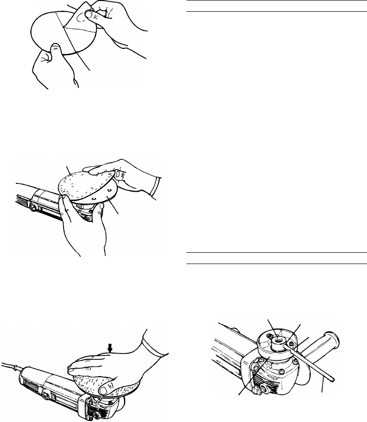
1. Insert the accessory bar wrench into the groove of
the spindle connector and the opening of the pad
spindle, as shown in Fig. 4.
2. Holding the bar wrench, the sanding pad is tightened
by rotating in to the right (clockwise), and loosened
by rotating it to the left (counterclockwise), as shown
in Fig. 5.
Fig. 1
Fig. 2
Fig. 3
Fig. 4
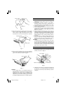
Lining paper
Slit part
Sanding paper
Sanding pad
Press strongly
Pad spindle
Opening
Groove
Spindle connector
Bar wrench
01Eng_SAY-150A_Eng 11/20/08, 11:125