


11
English
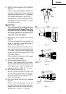
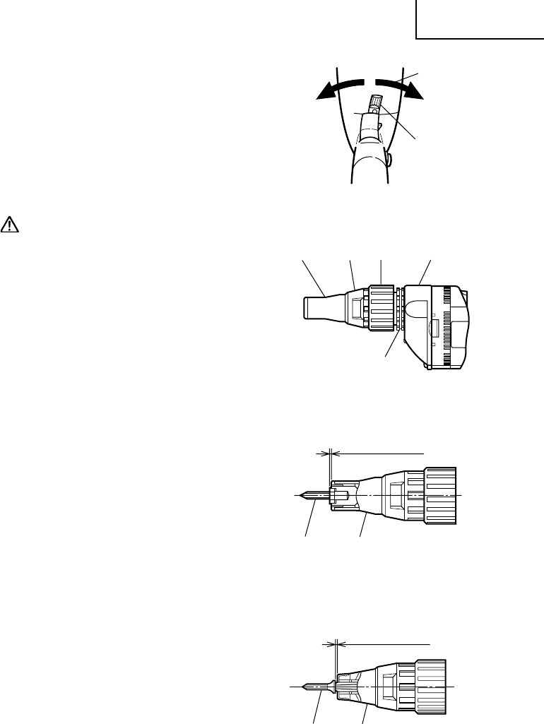
6. Confirm the direction of bit rotation
(Fig. 2)
The bit rotates clockwise (viewed from
the rear side) when the reversing
switch lever is set to the “R” side posi-
tion. When the lever is set to the “L”
side position, the bit rotates counter-
clockwise and can be used to loosen
and retract screws.
CAUTION:
Never change the bit rotating direction
while operating the Screw Driver. Turn
the main switch off before changing
the rotating direction, otherwise, burn-
ing of the motor will result.
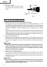
7. Adjusting the tightening depth
(Fig. 3)
Pull the lock sleeve in the direction of
arrow to remove it from the spline in-
stalled in the gear cover.
While pulling the lock sleeve and turn-
ing it right and left, adjust the position
of locator. Push the lock sleeve and
aligen the gear cover spline with the
lock sleeve spline.
The lock sleeve is inserted onto the gear
cover spline and locked.
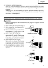
(1) For hex-head screws (Fig. 4)
Mount a hex-head screw on the hex-
socket and set the distance between the
sub-stopper end and the screw head
bottom to 0.04” – 0.06” (1 – 1.5 mm).
(2) For drywall screws (Fig. 5)
Mount a drywall screw on the bit, and
set the distance between the sub-stop-
per end and the screw head to 0.07” –
0.10” (2 – 2.5 mm).
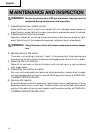
(3) For plus-head self-drilling screws
(Fig. 6)
Mount a self-drilling screw on the bit,
and set the distance between the sub-
stopper end and the screw head bot-
tom to 0.04” – 0.06” (1 – 1.5 mm).
Fig. 2
Fig. 4
Fig. 3
Fig. 5
1 – 1.5 mm
2 – 2.5 mm
R side
Lever
Sub
Stopper
Lock
sleeve
Locator Gear cover
Hex. head
screw
Sub-Stopper (B)
Drywall
screw
Sub-Stopper (A)