


English
10
OPERATION
1. Using the light equipped hook
CAUTION:
●
Do not attach the tip tool to the tool main unit when carrying the tool main unit with the light equipped
hook suspended from a waist belt.
Such action could result in injury.
The light equipped hook has the following two functions:
⅜
It can be used as a hook for suspending from a waist belt when required by the nature of the work.
⅜
It can be used as an auxiliary light for such operations as tightening screws in a dark place.
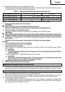
1.1 Using the hook
The hook can be installed on the right or left side and the angle can be adjusted in 5 steps between 0° and
80°.
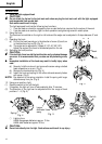
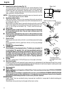
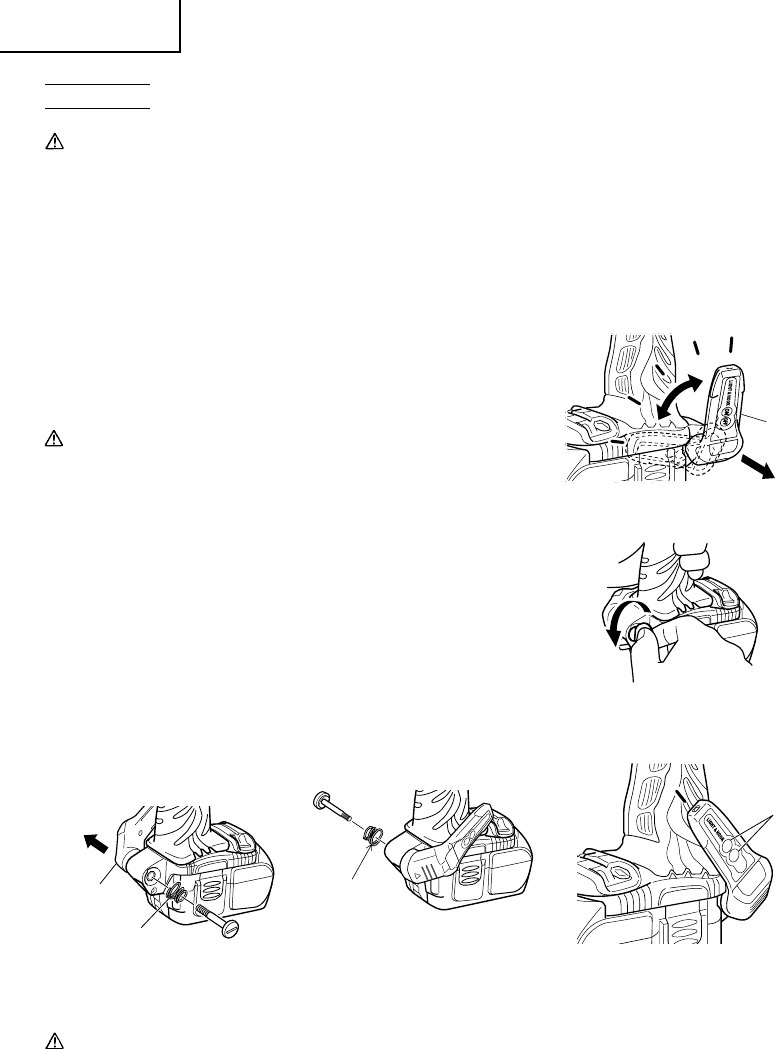
(1) Operating the hook
(a) Pull out the hook toward you in the direction of arrow (A) and turn
in the direction of arrow (B). (Fig. 2)
(b) The angle can be adjusted in 5 steps (0°, 20°, 40°, 60°, 80°).
Adjust the angle of the hook to the desired position for use.
(2) Switching the hook position
CAUTION:
●
If the tool falls, there is a risk that malfunction and/or physical damage
can occur. It is recommended that you also use fall-preventing wires,
etc.
●
Incomplete installation of the hook may result in bodily injury when
used.
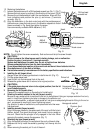
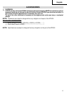
(a) Securely hold the main unit and remove the screw using a slotted
head screwdriver or a coin. (Fig. 3)
(b) Remove the hook and spring. (Fig. 4)
(c) Install the hook and spring on the other side and securely fasten
with screw. (Fig. 3)
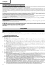
NOTE:
Pay attention to the spring orientation. Install the spring with larger
diameter away from you. (Fig. 5)
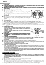
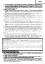
1.2 Using as an auxiliary light
(1) Press the switch to turn off the light.
If forgotten, the light will turn off automatically after 15 minutes.
(2) The direction of the light can be adjusted within the range of hook
positions 1 – 5. (Fig. 6)
⅜
Lighting time
AAAA manganese batteries: approx. 15 hrs.
AAAA alkali batteries: approx. 30 hrs.
CAUTION:
●
Do not look directly into the light. Such actions could result in eye injury.
Spring
Fig. 4
Fig. 3
Fig. 2
4
5
(A)
3
(
B
)
2
1
3
2
1
Hook
Fig. 5
Larger
diameter faces
away
3
3
Switch
Fig. 6