


4
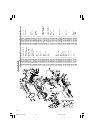
STANDARD ACCESSORIES
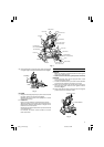
(1) 305 mm TCT Saw blade (mounted on tool) .............1
(2) Dust bag ......................................................................1
(3) 17 mm Box wrench ....................................................1
(4) Vise Assembly ............................................................1
(5) 4 mm Hex.bar wrench (only C12LCH/C12FCH) ........1
(6) Washer (C) ..................................................................1
Standard accessories are subject to change without notice.
OPTIONAL ACCESSORIES (SOLD SEPARATELY)
(1) Extension Holder and Stopper
(2) Crown molding Vise Ass'y (Include Crown molding
Stopper (L))
(3) Crown molding Stopper (L)
(4) Crown molding Stopper (R)
Optional accessories are subject to change without notice.
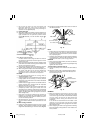
APPLICATION
⅜ Cutting various types of aluminium sash and wood.
UNPACKING
⅜ Carefully unpack the power tool and all related items
(standard accessories).
⅜ Check carefully to make certain all related items
(standard accessories) are present.
PRIOR TO OPERATION
1. Power source
Ensure that the power source to be utilized conforms
to the power requirements specified on the product
nameplate.
2. Power switch
Ensure that the power switch is in the OFF position. If
the plug is connected to a receptacle while the trigger
switch is in the ON position, the power tool will start
operating immediately, inviting serious accident.
3. Extension cord
When the work area is removed from the power
source, use an extension cord of sufficient thickness
and rated capacity. The extension cord should be kept
as short as practicable.
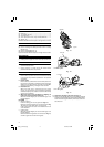
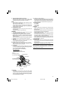
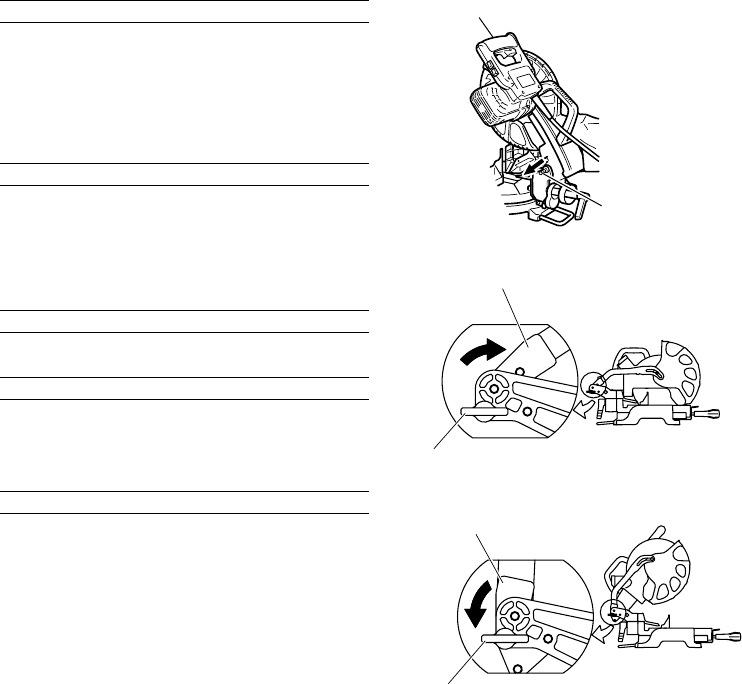
4. When the power tool is prepared for shipping, its
main parts are secured by a locking pin
Move the handle slightly so that the locking pin can
be disengaged.
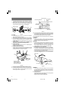
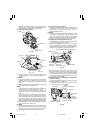
CAUTION
⅜ Set for transport
Lock the locking pin into the gear case (Fig. 1-a).
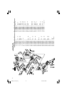
Remove a 6 mm wing bolt.Turn the link (C) as the Fig.
1-b, and fix it again with the 6 mm wing bolt.
Lower guard cover the teeth of the blade to the front
of the machine.
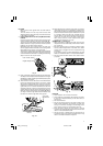
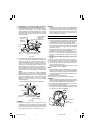
⅜ Cutting work
Move the handle slightly so that the locking pin can
be disengaged.
Remove a 6 mm wing bolt.Turn the link (C) as Fig. 1-c,
and fix it again with the 6 mm wing bolt.
Handle
Locking Pin
PullPull
Fig. 1-a
Fig. 1-b
Fig. 1-c
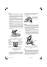
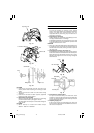
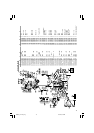
5. Attach the dust bag to the main unit (Fig. 2)
(1) When the dust bag has become full of sawdust, dust will
be blown out of the dust bag when the saw blade rotates.
Check the dust bag periodically and empty it before it
becomes full.
Link (C)
6 mm Wing Bolt
Link (C)
6 mm Wing Bolt
01Eng_C12LCH_Eng 4/11/07, 6:55 PM4