


7
CAUTION
Never lift the lower guard while the saw blade is
rotating.
The sub fence will not only make contact and
adversely affect cutting accuracy, this could also result
in damage to the guard.
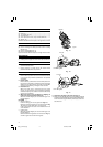
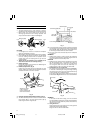
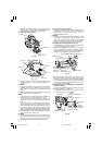
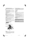
7. Position adjustment of laser line (Only Model C12LCH/
C12FCH)
Ink lining can be easily made on this tool to the laser
marker. A switch lights up the laser marker (Fig. 9).
Turning on the laser marker switch while the digital
display swich is on, light up the laser marker. (On the
C12FCH, only the laser marker switch.)
Depending upon your cutting choice, the laser line
can be aligned with the left side of the cutting width
(saw blade) or the ink line on the right side.
The laser line is adjusted to the width of the saw blade
at the time of factory shipment. Adjust the positions
of the saw blade and the laser line taking the following
steps to suit the use of your choice.
Fig. 9
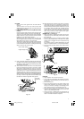
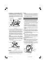
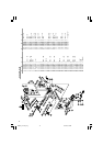
(1) Light up the laser marker and make a groove of about 5
mm deep on the workpiece that is about 38 mm in height
and 89 mm in width. Hold the grooved workpiece by vise
as it is and do not move it.
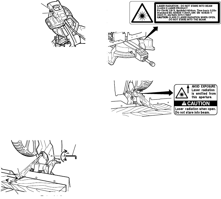
(2) Then insert a 4 mm hex. bar wrench in the 12 diameter
hole on the side of the gear case, turn the hex. socket
set screw to move the laser line. (If you turn the Hex.
socket screw clockwise, the laser line will shift to the
right and if you turn it counterclockwise, the laser line
will shift to the left.) When you work with the ink line
aligned with the left side of the saw blade, align the
laser line with the left end of the groove (Fig. 10). When
you align it with the right side of the saw blade, align
the laser line with the right side of the groove.
Fig. 10
(3) After adjusting the position of the laser line, draw a
right-angle ink line on the workpiece and align the
ink line with the laser line. When aligning the ink line,
slide the workpiece little by little and secure it by vise
at a position where the laser line overlaps with the
ink line. Work on the grooving again and check the
position of the laser line. If you wish to change the
laser line’s position, make adjustments again
following the steps from (1) to (3).
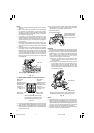
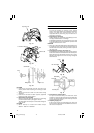
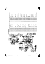
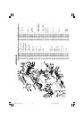
WARNING (Fig. 11 and Fig. 12)
⅜ Make sure before plugging the power plug into the
receptacle that the main body and the laser marker
are turned off.
⅜ Exercise utmost caution in handling a switch trigger
for the position adjustment of the laser line, as the
power plug is plugged into the receptacle during
operation.
If the switch trigger is pulled inadvertently, the saw
blade can rotate and result in unexpected accidents.
⅜ Do not remove the laser marker to be used for other
purposes.
Fig. 11
Fig. 12
CAUTION
⅜ Laser radiation - Do not stare into beam.
⅜ Laser radiation on work table. Do not stare into beam.
If your eye is exposed directly to the laser beam, it
can be hurt.
⅜ Do not dismantle it.
⅜ Do not give strong impact to the laser marker (main
body of tool); otherwise, the position of a laser line
can go out of order, resulting in the damage of the
laser marker as well as a shortened service life.
⅜ Keep the laser marker lit only during a cutting
operation. Prolonged lighting of the laser marker can
result in a shortened service life.
⅜ Use of controls or adjustments or performance of
procedures other than those specified herein may
result in hazardous radiation exposure.
Laser line
4 mm Hex.
Bar Wrench
Groove
Laser marker switch
Digital display switch
01Eng_C12LCH_Eng 4/11/07, 6:55 PM7