


11
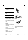
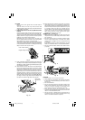
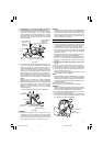
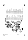
16.Confirmation for use Crown molding vise, Crown
molding Stopper (L) and (R) (Optional accessory)
(1) Crown molding Stopper (L) and (R) (optional
accessories) allow easier cuts of crown molding
without tilting the saw blade. lnstall them in the base
both-sides side to be shown in Fig. 24. After inserting
tighten the 6 mm knob bolts to secure the Crown
molding Stoppers.
Fig. 24
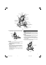
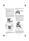
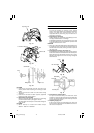
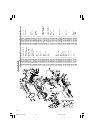
(2) The crown molding vise (B) (Optional accessory) can
be mounted on either the left fence (Fence (B)) or the
right fence (Fence (A)). lt can unite with the slope of
the crown molding and vice can be pressed down.
Then turn the upper knob, as necessary, to securely
attach the crown molding in position. To raise or lower
the vise assembly, first loosen the 6 mm wing bolt.
After adjusting the height, firmly tighten the 6 mm
wing bolt; then turn the upper knob, as necessary, to
securely attach the crown molding in position (See
Fig 25).
Position crown molding with its WALL CONTACT
EDGE against the guide fence and its CEILING
CONTACT EDGE against the Crown molding Stoppers
as shown in Fig. 25. Adjust the Crown molding
Stoppers according to the size of the crown molding.
Tighten the 6 mm wing bolt to secure the Crown
molding Stoppers.
Fig. 25
WARNING
⅜ Always firmly clamp or vise to secure the crown
molding to the fence; otherwise the crown molding
might be thrust from the table and cause bodily harm.
Do not bevel cutting. The main body or saw blade
may contact the sub fence, resulting in an injury.
CAUTION
⅜ Always confirm that the motor head (see Fig. 2) does
not contact the crown molding vise assembly when it
is lowered for cutting. If there is any danger that it
may do so, loosen the 6 mm knob bolt and move the
crown molding vise assembly to a position where it
will not contact the saw blade.
MOUNTING AND DISMOUNTING SAW BLADE
WARNING
⅜ To prevent an accident or personal injury, always turn off
the trigger switch and disconnect the power plug from
the receptacle before removing or installing a blade.
If cutting work is done in a state where the bolt is not
sufficiently tightened, the bolt can get loose, the blade
can come off, and the lower guard can get damaged,
resulting in injuries.
Also, check that the bolts are properly tightened before
plugging the power plug into the receptacle.
⅜ If the bolts are attached or detached using tools other
than the 17 mm box wrench (standard accessory),
excessive or improperly tightening occurs, resulting
in injury.
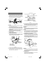
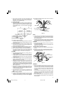
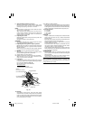
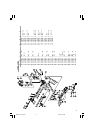
1. Mounting the saw blade (Fig. 26, Fig. 27, Fig. 28 and
Fig. 29)
(1) Rotate the lower guard (plastic) to the top position.
(2) Use the driver to loosen the 5 mm screw fastening
the spindle cover and then remove the spindle cover.
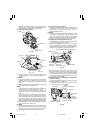
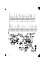
(3) Press in spindle lock and loosen bolt with 17 mm box
wrench (standard accessory).
Since the bolt is left-hand threaded, loosen by turning
it to the right as show in Fig. 28.
NOTE
⅜ If the spindle lock cannot be easily pressed in to lock the
spindle, turn the bolt with 17 mm box wrench (standard
accessory) while applying pressure on the spindle lock.
The saw blade spindle is locked when the spindle lock
is pressed inward.
(4) Remove the bolt and washer (B).
(5) Lift the lower guard and mount the saw blade.
WARNING
When mounting the saw blade, confirm that the rotation
indicator mark on the saw blade and the rotation direction
of the gear case (see Fig. 2) are properly matched.
(6) Thoroughly clean washer (B) and the bolt, and install
them onto the saw blade spindle.
(7) Press in the spindle lock and tighten the bolt by turning
it to the left by standard accessories wrench (17 mm
box wrench) as indicated in Fig. 28.
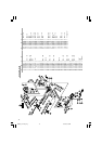
Fig. 26
Crown Molding Vise Ass’y (Optional accessory)
6 mm
Knob Bolt
Fence (B)
6 mm Wing
Bolt (A)
Crown molding
Knob
Crown Molding Stopper
(L) (R)
(Optional accessory)
Crown Molding
Vise Ass’y
(Optional
accessories)
6 mm Wing
Bolt
6 mm Wing
Bolt
Crown Molding Stopper (L)
(Optional accessories)
Crown Molding
Stopper (R)
(Optional
accessories)
6 mm Wing
Bolt
5 mm Machine
Screw
Spindle Cover
01Eng_C12LCH_Eng 4/11/07, 6:56 PM11