


8
NOTE
⅜ Perform cutting by overlapping the ink line with the
laser line.
⅜ When the ink line and the laser line are overlapped,
the strength and weakness of light will change,
resulting in a stable cutting operation because you
can easily discern the conformity of lines. This ensures
the minimum cutting errors.
⅜ In outdoor or near-the-window operations, it may
become difficult to observe the laser line due to the
sunlight. Under such circumstances, move to a place
that is not directly under the sunlight and engage in
the operation.
⅜ Do not tug on the cord behind the motor head or hook
your finger, wood and the like around it; otherwise,
the cord may come off and the laser marker may not
be lit up.
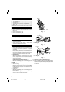
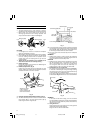
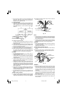
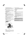
⅜ Check and make sure on a periodic basis if the position
of the laser line is in order. As regards the checking
method, draw a right-angle ink line on the workpiece
with the height of about 38 mm and the width of 89
mm, and check that the laser line is in line with the
ink line [The deviation between the ink line and the
laser line should be less than the ink line width (0.5
mm)] (Fig. 13).
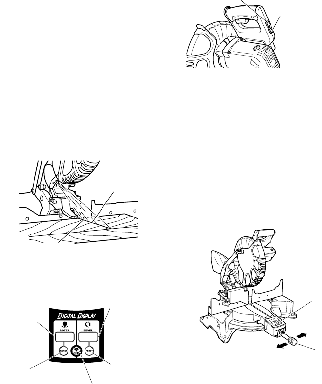
Fig. 13
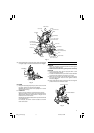
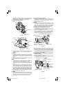
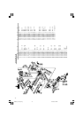
8. DIGITAL DISPLAY PANEL (for C12LCH and C12LC)
Fig. 14
(1) Turning on the digital display switch shows 0° for both
miter and bevel angle, regardless of main unit angle.
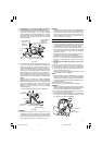
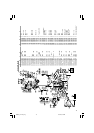
(2) Align the main unit angle with the tilt angle (0°) and
miter angle (0°) and hold down their reset buttons for
at least 0.2 seconds.
(3) Turning on the laser marker switch while the digital
display switch is on, lights up the laser marker. (On
the C12FCH, only the laser marker switch.)
Fig. 15
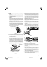
CAUTION
⅜ When operating the digital panel, have the motor head
section at the top limit position and the blade stopped.
⅜ If the figure shown on the miter angle digital display
is different from the positive stop angle (for example,
45.0° → 45.5°, 31.6° → 32.0°) then the positive stop
has probably deviated slightly from its correct
position. If this happens, do as follows.
(1) Move the turntable left and right with the side
handle loosened, and set the turntable to the
correct position.
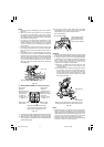
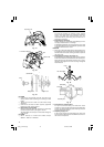
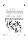
(2) If the figures on the display and positive stop still
do not match, then return the turntable to the 0°
position. Next move the turntable left and right
with the side handle loosened as shown in Fig.
15. After setting it to the correct position 0°, press
the reset button again.
Move the turntable left and right with the side
handle loosened and set it to the correct position.
Fig. 16
NOTE
⅜ Before starting to cut, align the main unit to the miter
angle 0° and the bevel angle 0° and hold down the
reset buttons for at least 0.2 seconds. If you press the
digital display switch to ON without aligning the main
unit to 0°, then the figures appearing on the digital
display and the main unit angle will not match.
⅜ The laser marker will not light up if the digital display
switch is turned off. (only on C12LCH)
Laser line
Marking (pre-marked)
Miter angle
window
(Displays arrows
show angle and
direction that
turntable is
rotating. Left is
←, Right is →.)
Bevel angle
window
(Displays arrows
showing motor
head bevel angle
and bevel
direction. Left is
←, Right is →.)
Miter angle
reset button
Bevel angle
reset button
Back light ON/OFF switch (Press
and the switch illuminates. Press
again and the lighting turns off.)
Laser marker switch
(for C12LCH/C12FCH)
Digital display switch
(for C12LCH/C12LC)
(Also serves as laser
marker power switch.)
Reset Button
Side Handle
01Eng_C12LCH_Eng 4/11/07, 6:55 PM8