


4
English
STANDARD ACCESSORIES
(1) Case ...........................................................................1
Standard accessories are subject to change without
notice.
OPTIONAL ACCESSORIES (sold separately)
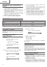
⅜ Demolishing
Bull point (Round type)
(SDS-plus shank)
Bull point (Square type)
(SDS-plus shank)
⅜ Groove digging and edging
Cold chisel (SDS-plus shank)
Cutter (SDS-plus shank)
⅜ Grooving
Grooving chisel (SDS-plus shank)
⅜ Hammer Grease A
500g (in a can)
70g (in a tube)
30g (in a tube)
Optional accessories are subject to change without
notice.
APPLICATIONS
Demolishing concrete, chiseling concrete, grooving, bar
cutting, and driving piles.
Application examples:
Installation of piping and wiring, sanitary facility
installation, machinery installation, water supply and
drainage work, interior jobs, harbor facilities and other
civil engineering work.
PRIOR TO OPERATION
1. Power source
Ensure that the power source to be utilized conforms
to the power requirements specified on the product
nameplate.
2. Power switch
Ensure that the power switch is in the OFF position.
If the plug is connected to a receptacle while the
power switch is in the ON position, the power tool
will start operating immediately, which could cause
a serious accident.
3. Extension cord
When the work area is removed from the power
source, use an extension cord of sufficient thickness
and rated capacity. The extension cord should be
kept as short as practicable.
4. Installing Tools
CAUTION
To prevent accidents, make sure to turn the switch
off and disconnect the plug from the receptacle.
NOTE:
When using tools such as bull points, cutters, etc.,
make sure to use the genuine parts designated by
our company.
(1) Clean the shank portion of the tool.
(2) Insert the tool in a twisting manner into the tool
holder until it latches itself. (Fig. 1, 2)
(3) Check the latching by pulling on the tool. (Fig. 3)
5. Deciding Working Position of Tool
The tool can be turned every 30 degrees and can
be fixed at the position of 12 steps.
(1) As shown in Fig. 4, grip (B) is turned 60 degrees
in the direction of A, the blade angle can be changed
freely to any desired position. (Fig. 5)
(2) As shown in Fig. 6, return grip (B) in the direction
of A, and make sure that it is locked completely.
6. Removing Tool
As shown in Fig. 7, pull front cap in the direction
of A, and pull out the tool. (Fig. 8)
SPECIFICATIONS
Voltage (by areas)* (110V, 115V, 120V, 127V, 220V, 230V, 240V)
Power Input 720W*
Full-load Impact Rate 0–3800/min.
Weight (without cord, side handle) 4.2 kg
* Be sure to check the nameplate on product as it is subject to change by areas.