


5
English
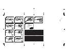
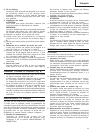
HOW TO USE THE HAMMER (Fig. 9)
1. After placing the tip of the tool on concrete surface,
switch ON.
The switch can be turned ON if the trigger is pulled
and OFF when it is released.
Impact rate of the tool can be controlled steplessly
by varying the amount that the trigger switch is
pulled.
2. By utilizing the empty weight of the machine and
by firmly holding the hammer by both hands, you
can effectively control the subsequent recoil motion.
Proceed at a moderate work-rate, the use of too
much pushing force will impair efficiency.
GREASE REPLACEMENT
This machine is of fully oil sealed construction to
protect against dust incursion and to prevent lubricant
leakage. This machine can be used without grease
replenishment for an extended period of time. However,
perform the grease replacement to extend the service
life. Replace the grease as described below.
1. Grease Replacement Period
You should look at the grease when you change
the carbon brush. (See item 4 in the section
MAINTENANCE AND INSPECTION.)
Ask for grease replacement at the nearest authorized
Hitachi Service Center.
In the case that you are forced to change the grease
by yourself, please follow the following points.
2. How to replace grease
CAUTION:
Before replacing the grease, turn the power off and
pull out the plug from the receptacle.
(1) Disassemble the crank cover and thoroughly wipe
off the old grease inside. (Fig. 10)
(2) Supply 30g (the standard volume to cover the
connecting rod) of Hitachi Electric Hammer Grease
A in the crank case.
(3) After replacing the grease, reassemble the crank
cover securely. At this time, do not damage or lose
the oil seal.
NOTE:
The Hitachi Electric Hammer Grease A is of the low
viscosity type. When the grease is consumed,
purchase from the authorized Hitachi Service
Center.
MAINTENANCE AND INSPECTION
CAUTION
To prevent accidents, make sure to turn the switch off
and disconnect the plug from the receptacle.
1. Inspecting the tool
Since use of a dull tool will degrade efficiency and
cause possible motor malfunction, sharpen or
replace the tool as soon as abrasion is noted.
2. Inspecting the mounting screws:
Regularly inspect all mounting screws and ensure
that they are properly tightened. Should any of the
screws be loose, retighten them immediately. Failure
to do so could result in serious hazard.
3. Maintenance of the motor
The motor unit winding is the very “heart” of the
power tool. Exercise due care to ensure the winding
does not become damaged and/or wet with oil or
water.
4. Inspecting the carbon brushes (Fig. 11)
The Motor employs carbon brushes which are
consumable parts. When they become worn to or
near the “wear limit”, it could result in motor trouble.
When an auto-stop carbon brush is equipped, the
motor will stop automatically. At that time, replace
both carbon brushes with new ones which have the
same carbon brush Number shown in the figure.
In addition, always keep carbon brushes clean and
ensure that they slide freely within the brush holders.
5. Replacing carbon brushes:
Loosen the set screw and remove the tail cover.
Remove the brush caps and carbon brushes. After
replacing the carbon brushes, do not forget to tighten
the brush caps properly and install the tail cover.
6. Service parts list
A: Item No.
B: Code No.
C: No. Used
D: Remarks
CAUTION
Repair, modification and inspection of Hitachi Power
Tools must be carried out by an Hitachi Authorized
Service Center.
This Parts List will be helpful if presented with the
tool to the Hitachi Authorized Service Center when
requesting repair or other maintenance.
In the operation and maintenance of power tools,
the safety regulations and standards prescribed in
each country must be observed.
MODIFICATIONS
Hitachi Power Tools are constantly being improved
and modified to incorporate the latest technological
advancements.
Accordingly, some parts (i.e. code numbers and/or
design) may be changed without prior notice.
NOTE
Due to HITACHI’s continuing program of research and
development, the specifications herein are subject to
change without prior notice.
IMPORTANT
Correct connection of the plug
The wires of the main lead are coloured in accordance
with the following code:
Blue: — Neutral
Brown: — Live
As the colours of the wires in the main lead of this
tool may not correspond with the coloured markings
identifying the terminals in your plug proceed as follows:
The wire coloured blue must be connected to the
terminal marked with the letter N or coloured black.
The wire coloured brown must be connected to the
terminal marked with the letter L or coloured red.
Neither core must be connected to the each terminal.