


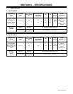
OM-210 088 Page 13
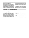
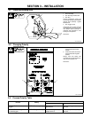
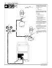
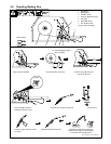
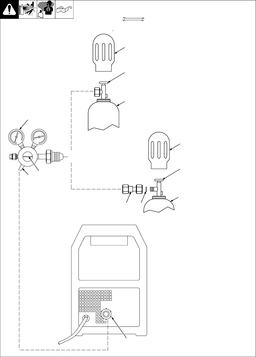
3-4. Installing Gas Supply
Obtain gas cylinder and chain to
running gear, wall, or other station-
ary support so cylinder cannot fall
and break off valve.
1 Cap
2 Cylinder Valve
Remove cap, stand to side of valve,
and open valve slightly. Gas flow
blows dust and dirt from valve.
Close valve.
3 Cylinder
4 Regulator/Flowmeter
Install so face is vertical.
5 Regulator/Flowmeter Gas
Hose Connection
6 Welding Power Source Gas
Hose Connection
Connect customer supplied gas
hose between regulator/flowmeter
gas hose connection, and fitting on
rear of welding power source.
7 Flow Adjust
Typical flow rate is 20 cfh (cubic feet
per hour). Check wire manufactur-
er’s recommended flow rate.
8CO
2
Adapter (Customer Sup-
plied)
9 O-Ring (Customer Supplied)
Install adapter with O-ring between
regulator/flowmeter and CO
2
cylinder.
Tools Needed:
CO
2
Gas
8 9
3
1
2
4
5
7
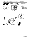
1
2
3
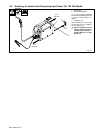
Argon Gas
OR
ST-802 028 / ST-802 086
5/8, 1-1/8 in
6