


. A complete Parts List is available at www.HobartWelders.com
OM-947 Page 23
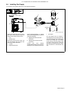
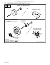
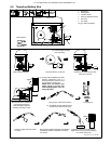
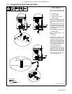
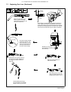
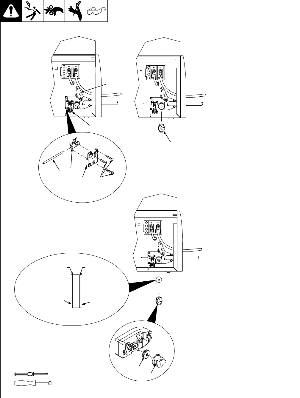
7-4. Changing Drive Roll Or Wire Inlet Guide
1 Pressure Adjustment Knob
2 Pressure Assembly
Pivot pressure adjustment knob
down, and lift pressure assembly
up.
3 Pivot Tube Plate
4 Securing Screws
5 Pressure Arm Pivot Tube
6 Inlet Wire Guide
Remove screws and pivot tube
plate. Lift out pressure arm pivot
tube, and slide inlet wire guide out of
tube.
Slide replacement wire guide into
tube, and place tube back into drive
assembly. Be sure tip of wire guide
is as close to drive roll as possible
without touching.
Reinstall plate and tighten screws.
7 Retaining Knob
Rotate counterclockwise and
remove knob.
8 Drive Roll
The drive roll consists of two
different sized grooves. Each side
is stamped with the proper size.
Select the groove that matches the
wire size on the wire spool. Install
drive roll onto motor shaft so that
correct groove size stamp faces out
away from drive housing.
9 Retaining Knob Opening
Install retaining knob by placing
opening over drive roll (opening
faces rear of unit). Rotate retaining
knob clockwise to secure drive roll.
Position wire into outer groove of
drive roll (see Section 5-9).
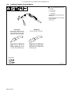
Tools Needed:
Ref. 802 444-B / 803 442-A
.024 Groove
.030/.035
VK
Groove
Stamped .024
Stamped .030/.035
1
3
4
5
6
2
7
5/16 in.
8
9