


OM-203 653 Page 21
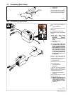
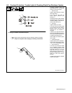
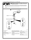
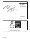
6-4. Checking/Replacing Retaining Cup, Tip, And Electrode
Overtightening will strip threads. Do not overtighten retaining cup during
assembly. Do not cross-thread parts causing stripping. Use care during torch
assembly and parts replacement.
Inspect shield cup, tip, and electrode for wear before cutting or whenever cutting speed has been significantly
reduced. Do not operate torch without a tip or electrode in place. Be sure to use genuine replacement parts.
A good practice is to replace both the tip and electrode at the same time.
802 465
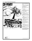
Turn Off power source.
1 Shield Cup
2 O-Ring
Remove shield cup. Check cup for cracks,
and replace if necessary.
Check O-ring for cracks or worn spots, re-
place shield cup if necessary.
3Tip
4 Opening
Remove tip. Check tip, and replace if open-
ing is deformed or 50% oversize. If inside of
tip is not clean and bright, clean with steel
wool. Be sure to remove any pieces of steel
wool afterwards.
5 Electrode
Check electrode. If center has a pit more
than a 1/16 in (2 mm) deep, remove and re-
place electrode.
6 Swirl Ring
7 O-Ring
Remove swirl ring. Check ring, and replace
if side holes are plugged.
Check O-ring for cracks or worn spots,
replace swirl ring if necessary.
8 O-Ring
Check O-ring for cracks or worn spots, and
replace if necessary.
Carefully reassemble parts in reverse order.
Make sure this area is clean of
any debris.
Make sure swirl ring is clean of any
debris and no holes are obstructed.
Turn Off power source before checking torch parts.
New
Worn
New
Worn
5
1/16 in
(2 mm)
Pit
4
3
6
1
2
7
8