


OM-180 670 Page 17
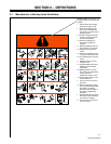
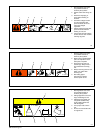
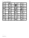
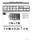
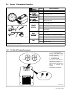
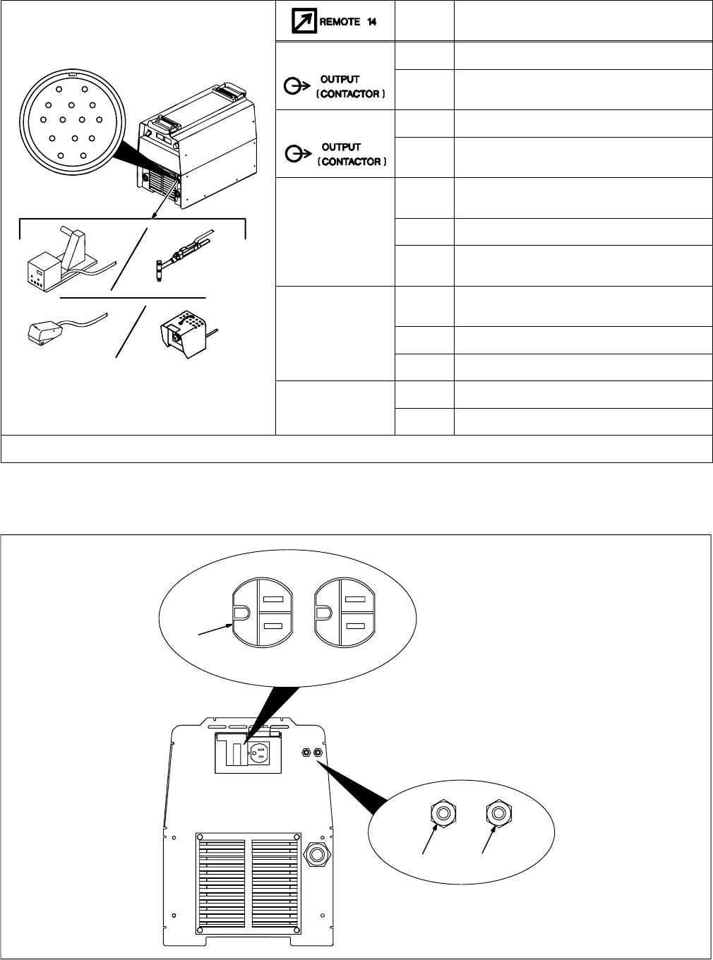
3-6. Remote 14 Receptacle Information
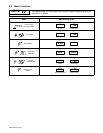
Socket* Socket Information
24 VOLTS AC
A 24 volts ac. Protected by circuit breaker CB2.
AJ
K
I
24 VOLTS AC
B Contact closure to A completes 24 volts ac con-
tactor control circuit.
B
I
C
L
NH
115 VOLTS AC
I 115 volts ac. Protected by circuit breaker CB1.
C
D
M
G
E
F
115 VOLTS AC
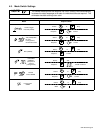
J Contact closure to I completes 115 volts ac con-
tactor control circuit.
C Output to remote control; 0 to +10 volts dc, +10
volts dc in MIG mode.
REMOTE
OUTPUT
D Remote control circuit common.
CONTROL
E 0 to +10 volts dc input command signal from re-
mote control.
A/V
H Voltage feedback; +1 volt dc per 10 output recep-
tacle volts.
A/V
AMPERAGE
VOLTAGE
F Current feedback; +1 volt dc per 100 amperes.
ST-801 192
VOLTAGE
M CC/CV select
G Circuit common for 24 and 115 volts ac circuits.
GND
K Chassis common.
*The remaining sockets are not used.
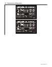
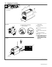
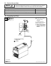
3-7. 110 Volt AC Duplex Receptacle
Ref. ST-801 245-A
1 110 V 7 A AC Receptacle
Power is shared between duplex
receptacle and Remote 14 recep-
tacle (see Section 3-6).
2 Circuit Breaker CB1
3 Circuit Breaker CB2
CB1 protects 110 volt ac portion of
duplex receptacle and Remote 14
receptacle from overload.
CB2 protects 24 volt ac portion of
Remote 14 receptacle from
overload.
Press button to reset breaker.
2 3
1