


OM-2208 Page 17
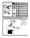
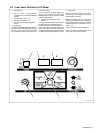
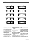
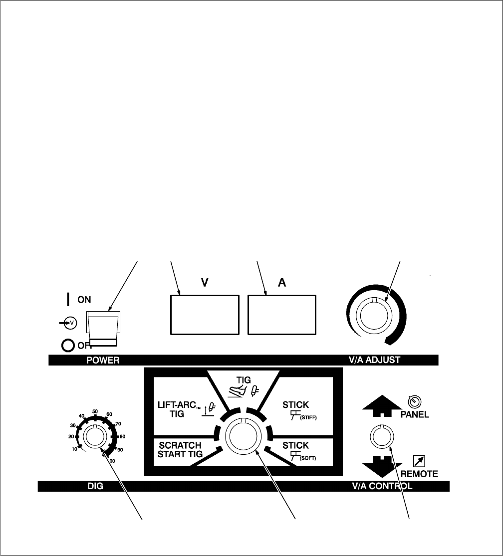
4-2. Front Panel Controls For CC Model
Ref. ST-175 500
23 4
5
1
7 6
1 Power Switch
. The fan motor is thermostatically
controlled and only runs when cooling is
needed.
2 Voltmeter (see Section 4-5)
3 Ammeter (see Section 4-5)
4 V/A (Voltage/Amperage) Adjustment
Control
5 Mode Switch
The Mode switch setting determines both the
process and output On/Off control (see Sec-
tion 4-6). Source of control (panel or remote)
for the amount of output is selected on the
V/A Control switch.
For Air Carbon Arc (CAC-A) cutting and
gouging, place switch in one of the Stick
positions. For best results, place Dig control
in the maximum position.
6 V/A (Voltage/Amperage) Control
Switch
For front panel control, place switch in Panel
position and use the V/A Adjust control.
For remote control, make connections to Re-
mote 14 receptacle, and place switch in Re-
mote position. Remote control is a percent of
V/A Adjust control setting. Value selected on
V/A Adjust is maximum available on remote.
7 Dig Control
When set towards minimum, short-circuit
amperage at low arc voltage is the same as
normal welding amperage.
When set towards maximum, short-circuit
amperage is increased at low arc voltage to
assist with arc starts as well as reduce stick-
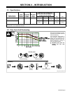
ing while welding (see volt-ampere curves in
Section 2-3).
Select setting best suited for application.
When a TIG process is selected on the mode
switch, this control is not functional.