


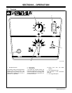
OM-227 978 Page 15
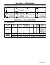
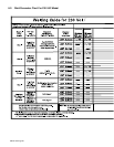
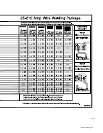
5-7. Electrical Service Guide
Input Voltage 230
Input Amperes At Rated Output 24
Max Recommended Standard Fuse Or Circuit Breaker Rating In Amperes
Circuit Breaker
1
, Time-Delay
2
25
Normal Operating
3
35
Min Input Conductor Size In AWG
4
14
Max Recommended Input Conductor Length In Feet (Meters)
55
(17)
Min Grounding Conductor Size In AWG 14
Reference: 2005 National Electrical Code (NEC) (including article 630)
1 Choose a circuit breaker with time-current curves comparable to a Time Delay Fuse.
2 “Time-Delay” fuses are UL class “RK5” .
3 “Normal Operating” (general purpose - no intentional delay) fuses are UL class “K5” (up to and including 60 amp), and UL class “H” ( 65 amp and
above).
4 Conductor data in this section specifies conductor size (excluding flexible cord or cable) between the panelboard and the equipment per NEC Table
310.16. If a flexible cord or cable is used, minimum conductor size may increase. See NEC Table 400.5(A) for flexible cord and cable requirements.
Y Caution: Failure to follow these fuse and circuit breaker recommendations could create an electric shock or fire hazard. These
recommendations are for a dedicated branch circuit that applies to the rated output and duty cycle of the welding power source.
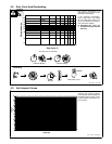
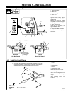
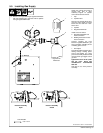
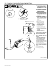
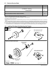
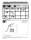
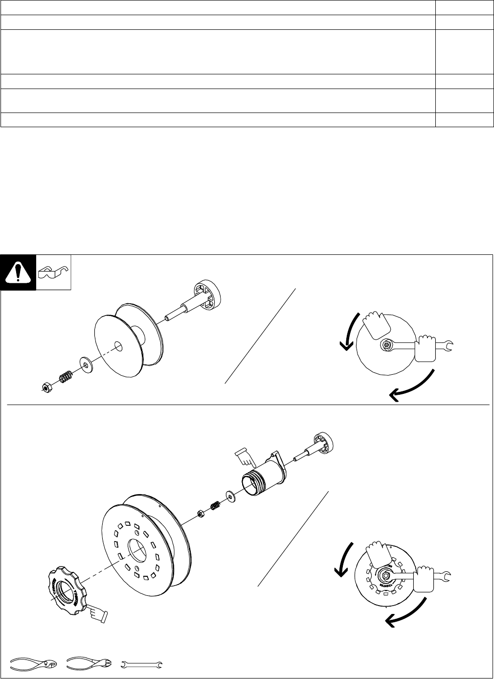
5-8. Installing Wire Spool And Adjusting Hub Tension
When a slight force is needed
to turn spool, tension is set.
1/2 in
Tools Needed:
803 012 / 803 013 -B / Ref. 802 971-C
Installing 8 in (203 mm) Wire Spool
Installing 4 in (102 mm) Wire Spool
When a slight force is needed
to turn spool, tension is set.
Retaining ring used
with 8 in (203 mm)
spool only.
Adapter used with
8 in (203 mm)
spool only.