


OM-227 978 Page 23
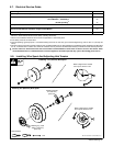
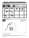
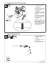
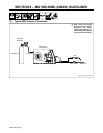
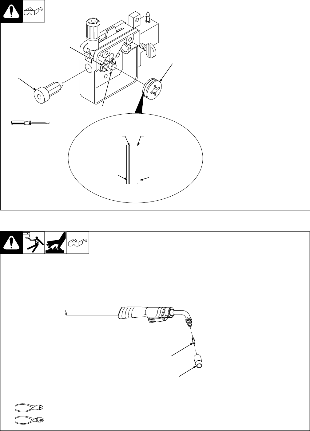
7-4. Changing Drive Roll Or Wire Inlet Guide
1 Inlet Wire Guide Securing
Screw
2 Inlet Wire Guide
Loosen screw. Slide tip as close to
drive rolls as possible without
touching. Tighten screw.
3 Retaining Pin
To remove drive roll, push drive roll
in and rotate it (1/4 turn) to the open
slot and slide it out over the
retaining pin.
To secure drive roll, locate open slot
and push drive roll completely over
retaining pin, then rotate drive roll
(1/4 turn) to closed slot.
4 Drive Roll
The drive roll consists of two
different sized grooves. The
stamped markings on the end
surface of the drive roll refers to the
groove on the opposite side of the
drive roll. The groove closest to the
motor shaft is the proper groove to
thread (see Section 5-11).
Tools Needed:
Ref. 803 714-A
.023/.025 Groove.030/.035 Groove
Stamped .024
Stamped .030/.035
3
1
2
4
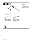
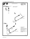
7-5. Replacing Gun Contact Tip
Ref. 802 399-A
Y Turn Off power before
replacing contact tip.
1 Nozzle
2 Contact Tip
Cut off welding wire at contact tip.
Remove nozzle.
Remove contact tip and install new
contact tip. Reinstall nozzle.
Tools Needed:
1
2