


OM-279 Page 11
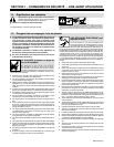
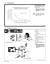
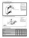
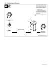
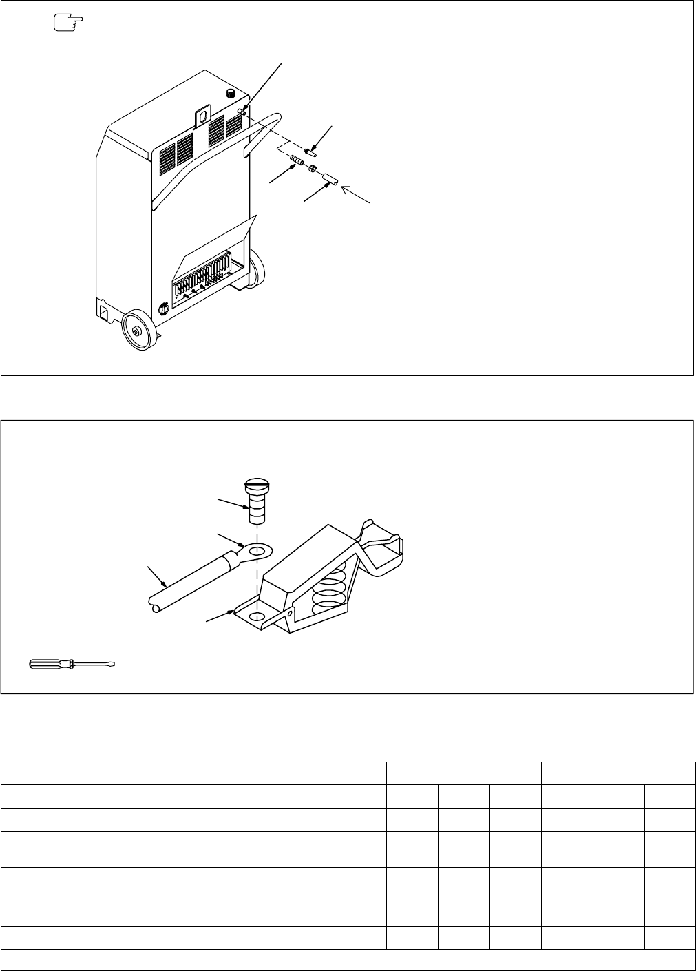
2-6. Connecting Gas/Air Supply
1 Unit Gas Fitting (Female 1/4
NPT)
2 Quick Connect Gas Fitting
3 Standard Gas Fitting
Obtain and install desired fitting.
4 Hose
Obtain suitable hose according to
installed fitting, and connect to fit-
ting. Route hose to gas/air supply.
Adjust gas/air pressure according
to Section 3-2.
Y Incorrect plasma gas can
cause torch and power
source damage. Use only air
or nitrogen for the plasma
gas.
Ref. ST-801 455
From Gas/Air Supply
3
Use only clean and dry gas/air with 70 to 150 psi
(483 to 1034 kPa) pressure.
2
1
4
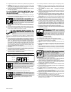
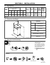
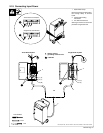
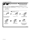
2-7. Installing And Connecting Work Clamp
ST-800 958
1 Work Cable From Unit
2 Ring Terminal
3 Screw
4 Work Clamp Handle
Connect ring terminal end of cable
to handle using screw.
Connect work clamp to a clean,
paint-free location on workpiece, as
close to cutting area as possible.
Tools Needed:
1
2
3
4
2-8. Electrical Service Guide
Single-Phase Models Three-Phase Models
Input Voltage
200 230 460 230 460 575
Input Amperes At Rated Output
42.3 36.8 18.4 18.4 9.2 7.4
Max Recommended Standard Fuse Or Circuit Breaker Rating In
Amperes
60 60 30 30 15 10
Min Input Conductor Size In AWG/Kcmil
8 10 14 14 14 14
Max Recommended Input Conductor Length
In Feet (Meters)
110 (33) 97 (29) 153 (47) 66 (20) 266 (81)
415
(127)
Min Grounding Conductor Size In AWG/Kcmil
10 10 14 14 14 14
Reference: 1993 National Electrical Code (NEC) S-0092-J