


OM-925 Page 21
Return To Table Of Contents
217 618-A
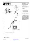
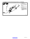
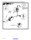
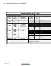
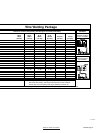
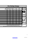
Wire Welding Package
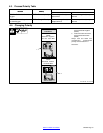
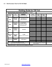
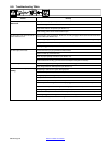
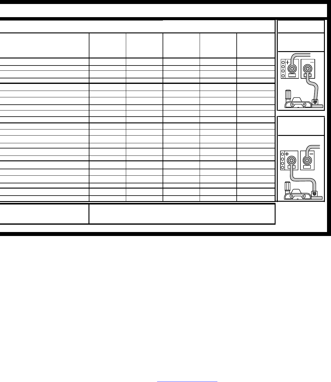
Recommended Voltage and Wire Speed Settings for thickness of metal being welded.
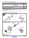
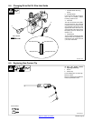
CHANGING
POLARITY
DCEN
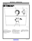
20 ga. 18 ga. 16 ga. 11 ga.
Number left of slash is Voltage Setting / Number right of slash is Wire Feed Setting.
Electrode Negative
.036 in. .048 in. .060 in. 1/8 inch 3/16 inch 1/4 inch For Flux Cored Wire
(0.8 mm) (1.2 mm) (1.6 mm) (3.2 mm) (4.8 mm) (6.4 mm)
~ 1 / 30 2 / 30 3 / 40 4 / 45 ~
~ ~ 2 / 20 3 / 20 4 / 35 4 / 50*
2 / 30 3 / 40 3 / 50 4 / 70 ~
~
2 / 20 2 / 30 3 / 35 4 / 40 ~
~
~
3 / 25 3 / 30 4 / 40 ~ ~
2 / 30 3 / 30 3 / 40 4 / 40 ~ ~
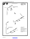
DCEP
For Solid Wire
Electrode Positive
~ 3 / 20 4 / 30 4 / 35 ~ ~
~ ~ 4 / 25 4 / 30 ~ ~
~ 2 / 30 3 / 40 4 / 50 ~ ~
~ 2 / 15 3 / 10 4 / 30 ~ ~
~ ~ 3 / 90** 4 / 90** ~ ~
Wire Speed listed is a starting value only. Wire Speed setting can be
fine−tuned while welding. Wire Speed also depends on other variables
such as stick out, travel speed, weld angle, cleanliness of metal, etc.
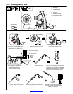
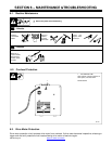
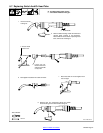
Make sure that hub tension is not too tight and keep the torch straight as possible. A ”push angle” for the torch is recommended.