


TM-944 Page 18 Handler 135 / 175
Return To Table Of Contents
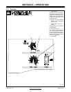
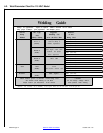
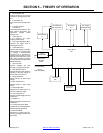
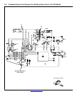
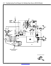
1 Circuit Breaker CB1
Protects unit from an over-current
condition by opening primary power
line.
2 Power Switch S1
Turns unit and fan motor FM on and
off.
3 Fan Motor FM And
Transformer
Controlled by power switch S1. Fan
cools internal components, and
transformer supplies control
voltage to PC1.
4 Thermostat TP1
If unit overheats, TP1 opens
stopping all weld output.
5 Gun Trigger Receptacle RC3
Connects gun trigger circuit to
welding power source.
6 Control Board PC1
Controls weld output by connecting
primary power to main transformer
T1 through a board-mounted
contactor that is activated by
pressing the gun trigger. PC1 also
regulates wire feed motor speed
with a motor control circuit. Speed
is set by feedback from Wire Feed
Speed Control R1.
7 Gas Valve GS1
Controls shielding gas flow.
Pressing gun trigger opens valve.
8 Wire Speed Control R1
Controls wire feed motor speed by
providing a reference voltage to
motor control circuit on PC1.
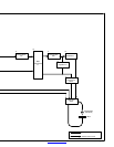
9 Range Switch S2
Allows selection of weld output
voltage.
10 Main Transformer T1
Supplies power to weld output
circuit.
11 Main Rectifier SR1
Changes the ac output from T1 to
full-wave rectified dc output.
12 Output Capacitor C1
Smooths dc weld voltage from main
rectifier SR1.
13 Stabilizer L1
Smooths dc weld current from main
rectifier SR1.
14 Polarity Changeover Block
Terminals allow changing between
DCEP and DCEN processes.
15 Wire Drive Motor
Feeds wire at a speed set by R1.
Pressing gun trigger activates wire
drive motor.
SECTION 5 − THEORY OF OPERATION
2
34
7
Single-Phase
Line Input
Power
1
Circuit
Breaker CB1
5
Power Switch
S1
Gas Valve
GS1
8
Wire Speed
Control R1
Line
L1
Neutral Line
(115 VAC Model)
Fan Motor FM
And Transformer
Thermostat
TP1
Gun Trigger
Receptacle RC3
Control Board
PC1
6
Line L2
(230 VAC Models)