


TM-944 Page 29Handler 135 / 175
Return To Table Of Contents
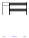
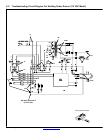
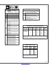
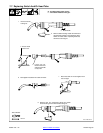
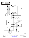
6-7. Control Board PC1 Test Point Values (230 VAC Model)
PC1 Voltage Readings
a) Tolerance −
±10% unless
specified
b) Reference − to circuit common
unless noted
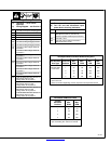
Voltage Readings:
a) Tolerance − ±10% unless specified b) Reference − as noted
Receptacle Pin Value
RC1 1 24 volts ac input, reference to pin RC1-2
2 24 volts ac input, reference to pin RC1-1
3,4 35 volts dc with transformer thermostat closed, reference to pin TP-C
5 35 volts dc with gun trigger closed, reference to TP-C
6 35 volts dc, reference to TP-C
7 15.0 volts dc, reference to TP-C
8 15.0 to 6.5 volts dc from min to max of Wire Feed speed control R1, Reference for TP-C
RC2
1 Negative (−) welder output voltage
2 Not used
3 Positive (+) output to wire drive motor
4 Negative (−) output to wire drive motor
RC4 −− Circuit common
RC5 −− Positive (+) welder output voltage with gun trigger closed
TP A 35 volts dc, reference to TP-C
TP B 15 volts dc, reference to TP-C
TP C Circuit common
TP D 30 volts dc, reference to TP-C
TP E 15 volts dc with Wire Speed control R1 at minimum, reference to TP-C
TP F 11 volts dc with Wire Speed control R1 at maximum, reference to TP-C