


OM-353 Page 18
1
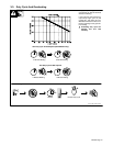
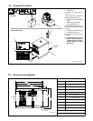
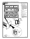
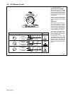
3-11. Placing Jumper Links And Connecting Input Power
ST-117 263-K
Check input voltage available at
site.
1 Jumper Link Label
Check label inside your unit–
only one label is on unit.
Y Only make connections for
the voltages shown on the la-
bel inside your unit. Do not
make connections for any
other voltages. If jumper link
label is missing from inside
unit, check rating label (see
Section 3-4) for allowable in-
put voltages.
2 Jumper Links
Move jumper links to match input
voltage.
3 Input And Grounding
Conductors
Select size and length using
Section 3-10.
4 Line Disconnect Device
Select type and size of overcurrent
protection using Section 3-10.
Reinstall side panel.
Y Special installation may be
required where gasoline or
volatile liquids are present –
see NEC Article 511 or CEC
Section 20.
3/8 in
3/8, 1/2, 7/16 in
Tools Needed:
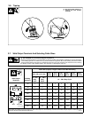
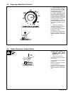
230 VOLTS
LL
460 VOLTS
LL
S-010 587-B
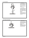
575 VOLTS
LL
230 VOLTS 460 VOLTS200 VOLTS
LL LL LL
S-083 566-C
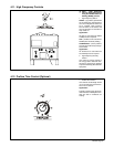
2
L1 (U)
L2 (V)
GND/PE
Earth Ground
4
3
220 VOLTS
LL
380 VOLTS
LL
S-131 783-A
415 VOLTS
LL
Connect GND/PE
Conductor First
Connect GND/PE
Conductor First
S-047 672-A
260 VOLTS
LL
380 VOLTS
LL
520 VOLTS
LL