


OM-353 Page 31
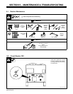
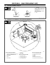
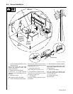
6-3. Correct Installation
1 HF Source (Welder With Built-In HF Or
Separate HF Unit)
Ground metal machine case, work output
terminal, line disconnect device, input
supply, and worktable.
2 Welding Zone And Centerpoint
A circle 50 ft (15 m) from centerpoint
between HF source and welding torch in all
directions.
3 Weld Output Cables
Keep cables short and close together.
4 Conduit Joint Bonding And Grounding
Electrically join (bond) all conduit sections
using copper straps or braided wire. Ground
conduit every 50 ft (15 m).
5 Water Pipes And Fixtures
Ground water pipes every 50 ft (15 m).
6 External Power Or Telephone Lines
Locate HF source at least 50 ft (15 m) away
from power and phone lines.
7 Grounding Rod
Consult the National Electrical Code for
specifications.
8 Metal Building Panel Bonding Methods
Bolt or weld building panels together, install
copper straps or braided wire across seams,
and ground frame.
9 Windows And Doorways
Cover all windows and doorways with
grounded copper screen of not more than
1/4 in (6.4 mm) mesh.
10 Overhead Door Track
Ground the track.
Ref. S-0695 / Ref. S-0695
1
2
50 ft
(15 m)
Weld Zone
3
6
50 ft
(15 m)
7
4
7
5
Ground
Workpiece
If Required
By Codes
Ground All
Metal Objects
And All Wiring
In Welding Zone
Using #12 AWG
Wire
Nonmetal
Building
8
10
9
Metal Building
7
7