


C7400S ENTHALPY SYLK BUS SENSOR
62-0332—03 2
BEFORE INSTALLATION
Review the “Specifications” on page 1 before installing the
sensor.
When Installing This Product
1. Read these instructions carefully. Failure to follow them
could damage the product or cause a hazardous
condition.
2. Check ratings given in instructions and on the product to
ensure the product is suitable for your application.
3. Installer must be a trained, experienced service
technician.
INSTALLATION AND SETUP
The following installation procedures should be performed in
the order listed:
1. Mounting — see “Mounting” on this page.
2. Wiring — see “Wiring” on page 3.
3. Checkout — see “Checkout” on page 3.
MOUNTING
IMPORTANT
Avoid mounting in areas where acid fumes or other
deteriorating vapors can attack the metal parts of the
sensor, or in areas where escaping gas or other
explosive vapors are present.
IMPORTANT
The sensor must be mounted in a position that
allows clearance for wiring, servicing, and removal.
The sensor is mounted directly to the sheet metal using self
tapping sheet metal screws or in the air stream using the duct
mounting kit. Use #6 or #8 screws (screws are not provided
and must be obtained separately). Use the dimensions in
Fig. 1 on page 1 as a guide.
The sensor must be mounted to allow air flow through the
sensor housing vent slots on the end or side.
The Sylk Bus sensor communicates with a controller (such as
the JADE™ Economizer Model W7220) on the two-wire
communication bus and can either be wired using a two pin
header or using a side connector. The unit pack Sylk Bus
sensor includes a two pin Euro connector with the packaging.
The SKU number of the Sylk Bus sensor is C7400S. All OAT
(Outdoor Air Temperature), RAT (Return Air Temperature) and
DAT (Discharge Air Temperature) sensors are the same SKU
number. The sensor is set for the appropriate type of sensing
using the three position DIP switch located on the sensor.
OAT position is OFF, OFF, OFF; RAT is ON, OFF, OFF and
DAT is OFF, ON, OFF. During installation the sensors are set
for the the appropriate usage. See “Sylk Bus Sensor Wiring”
on page 3 for DIP switch details.
Once installed, a sensor can be changed to a different
application by simply changing the DIP switch setting.
Sensor Mounting
The sensor can be mounted directly on to the sheet metal of
the unit or can be mounted in the air stream using the duct
mounting kit.
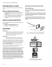
The duct mounting kit contains a rod to hold the sensor in the
duct, a flange to secure the sensor rod to the duct wall and to
fill the hole, and a gasket to prevent air from leaking through
the duct wall. See Fig. 2.
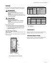
The rod has slots for threading the wire to prevent loose or
hanging wire in the duct and can be adjusted for 6 or 12 inch
length. The flange has extended relief for ease of mounting.
See Fig. 3.
Fig. 2. Duct Mounting Kit (Part # 50053060-001).
Fig. 3. Duct Mounting Adjustments.
ROD - 1 PIECE
FLANGE - 1 PIECE
GASKET - 1 PIECE
M32281
WIRE HOLDER
EXTENDED RELIEF
(FOR CORRECT MOUNTING)
M32282
LENGTH ADJUSTS
TO 6 OR 12 INCHES