


C7400S ENTHALPY SYLK BUS SENSOR
3 62-0332—03
WIRING
All wiring must comply with applicable electrical codes and
ordinances, or as specified on installation wiring diagrams.
WARNING
Electrical Shock Hazard.
Can cause severe injury, death or property
damage.
Disconnect power supply before beginning wiring, or
making wiring connections, to prevent electrical shock
or equipment damage.
CAUTION
Equipment Damage Hazard.
Electrostatic discharge can short equipment
circuitry.
Ensure that you are properly grounded before
handling the sensor.
Prepare wiring as follows:
1. Strip 1/2 in. (13 mm) insulation from the conductor.
2. Cut a single wire to 3/16 in. (5 mm). Insert the wire in
the required terminal location and tighten the screw.
3. Pull on each wire in all terminals to check for good
mechanical connection.
Sylk Bus Sensor Wiring
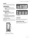
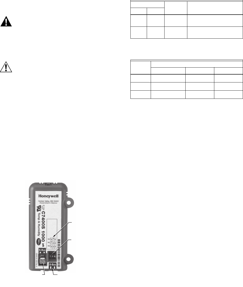
Use Fig. 4 and Table 1 to locate the wiring terminals for each
Sylk Bus sensor.
Use Fig. 4 and Table 2 to set the DIP switches for the desired
use of the sensor.
Fig. 4. Sylk Bus sensor DIP switches.
CHECKOUT
Refer to the JADE™ Economizer Module (Model W7220)
Installation Instructions (Honeywell form 62-0331).
TROUBLESHOOTING
Refer to the JADE™ Economizer Module (Model W7220)
Installation Instructions (Honeywell form 62-0331).
DIP
SWITCH
LABEL
M32271
SYLK BUS
TERMINALS
(1 AND 2)
DIP
SWITCHES
(3)
SYLK BUS
2 PIN “EURO”
CONNECTOR
Table 1. SYLK Bus Sensor Wiring Terminations
a
.
a
Terminals are polarity insensitive.
Terminal
Type DescriptionNbr Label
1 S-BUS SYLK Bus Sylk Bus Communications
(Sensor Bus)
2 S-BUS SYLK Bus Sylk Bus Communications
(Sensor Bus)
Table 2. SYLK Bus Sensor DIP Switch Settings.
Use
DIP Switch Positions for Switches 1, 2, & 3
123
DA
a
a
DA = Discharge Air
OFF ON OFF
RA
b
b
RA = Return Air
ON OFF OFF
OA
c
c
OA = Outside Air
OFF OFF OFF