


15
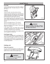
1. WASHER (1)
2. COTTER PIN (1)
3. BRAKE HANDLE
4. BRAKE ROD ASSEMBLY
SET-UP
Equipment set-up
1. Remove crate top and sides.
2. Remove upper handle bar assembly and lay
aside.
3. Open bag containing loose hardware.
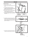
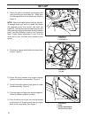
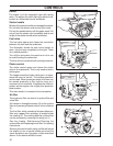
4. Using four (4) screws, flat washers and nuts
attach the upper handle bar assembly to lower
handle bar assembly. See Figure 1.
NOTE: Handle fit is tight. When aligning holes use
a tapered type pilot to help align holes (i.e.
punch or phillips style screw driver).
5. Attach the position adjusting rod to bracket on
the lower and upper handle bar assemblies.
See Figure 1.
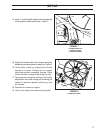
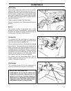
6. Assemble the compression spring, two (2) flat
washers and yoke to brake rod assembly. See
Figure 2. Screw yoke onto the rod assembly
till rod is even or thru threaded portion of yoke
about 1/4” (6.35 mm).
7. Attach brake rod assembly to brake handle on
the upper handle bar assembly. See Figure 3.
FIGURE 1
FIGURE 2
FIGURE 3
1. WASHERS
3. SPRING
2. YOKE
4. BRAKE ROD ASSEMBLY
7. HARDWARE
6. LOWER HANDLE BAR
4. ADJUSTING ROD
1. WASHERS (2)
3. UPPER HANDLE BAR
2. COTTER PINS (2)
5. COTTER PIN (1)
1
2
3
4
5
6
7
1
2
3
4
1
2
3
4