


16
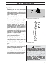
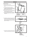
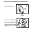
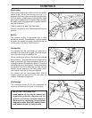
8. Attach the yoke to the brake’s top mounting hole
using the clevis pin and cotter pin. Make sure
the rod is positioned in the bracket as shown in
Figure 4.
SET-UP
FIGURE 4
NOTE: Adjust the brake before inserting hair pin.
To engage brake, pull back on handle until brake
rod assembly goes “over center” and locks the
brake ON. Turning the yoke clockwise shortens the
rod tightening the grip on the brake disc by the brake
pads. counterclockwise loosens the clamping
force. Proper brake adjustment is such that the
wheel will not turn, but slide, when handle is over
center.
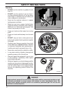
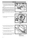
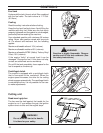
9. Remove air cleaner and double wire clamp from
engine. Figure 5.
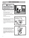
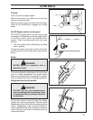
10. Route the wire harness from engine through
guide and handle crossmember. Figure 6.
11. Route the throttle cable through guide on lower
handle assembly. Figure 6.
12. Connect upper and lower wire harness together.
Yellow to yellow and black to black.
13. Push throttle control lever on console forward
to full extent. Pull throttle control lever on engine
back as far as possible. See Figure 7.
FIGURE 5
FIGURE 6
1. CLAMP
2. THREAD WIRE HARNESS
AND THROTTLE CABLE
1. GUIDE
2. CLEVIS PIN (1)
1. HAIR PIN (1)
1
2
1
1
2