


English
11
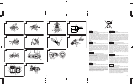
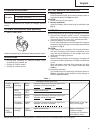
(b) The direction of the light can be adjusted within
the range of hook positions 1 - 5. (Fig. 12)
⅜ Lighting time
AAAA manganese batteries: approx. 15 hrs.
AAAA alkali batteries: approx. 30 hrs.
CAUTION:
Do not look directly into the light.
Such actions could result in eye injury.
(4) Replacing the batteries
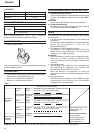
(a) Loosen the hook screw with a phillips-head
screwdriver (No. 1). (Fig. 13)
Remove the hook cover by pushing in the direction
of the arrow. (Fig. 14)
(b) Remove the old batteries and insert the new
batteries. Align with the hook indications and
position the plus (+) and minus (–) terminals
correctly. (Fig. 15)
(c) Align the indentation in the hook main body with
the protuberance of the hook cover, press the
hook cover in the direction opposite to that of the
arrow shown in Fig. 14 and then tighten the screw.
Use commercially available AAAA batteries
(1.5 V).
NOTE:
Do not tighten the screw excessively. Such action
could strip the screw threads.
CAUTION:
⅜ Failure to observe the following can result in battery
leakage, rust or malfunction.
Position the plus (+) and minus (–) terminals correctly.
Replace both batteries at the same time. Do not mix
old and new batteries.
Remove exhausted batteries from the hook
immediately.
⅜ Do not discard batteries together with normal trash
and do not throw batteries into fire.
⅜ Store batteries out of the reach of children.
⅜ Use batteries correctly in accordance with the battery
specifications and indications.
7. Mounting and dismounting of the bit
(1) Mounting the bit
Loosen the sleeve by turning it toward the left (in the
counterclockwise direction as viewed from the front)
to open the clip on the keyless chuck. After inserting
a driver bit, etc., into the keyless drill chuck, and
tighten the sleeve by turning it toward the right (in
the clockwise direction as viewed from the front).
(See Fig. 16)
⅜ If the sleeve becomes loose during operation, tighten
it further.
The tightening force becomes stronger when the
sleeve is tightened additionally.
(2) Dismounting the bit
Loosen the sleeve by turning it toward the left (in the
counterclockwise direction as viewed from the front),
and then take out the bit ect. (See Fig. 16)
NOTE:
If the sleeve is tightened in a state where the clip of
the keyless chuck is opened to a maximum limit, a
click noise may occur. This is the noise that occurs
when the loosening of the keyless chuck is prevented
and is not a malfunction.
CAUTION:
⅜ When it is no longer possible to loosen the sleeve,
use a vise or similar instrument to secure the bit. Set
the clutch mode between 1 and 11 and then turn the
sleeve to the loose side (left side) while operating the
clutch. It should be easy now to loosen the sleeve.
8. Automatic spindle-lock mechanism
This unit has automatic spindle-lock mechanism for
quick bit changes.
9. Confirm that the battery is mounted correctly
10. Check the rotational direction
The bit rotates clockwise (viewed from the rear side)
by pushing the R-side of the selector button.
The L-side of the selector button is pushed to turn the
bit counterclockwise. (See Fig. 17) (The
L
and
R
marks are provided on the selector button.)
11. Switch operation
⅜ When the trigger switch is depressed, the tool rotates.
When the trigger is released, the tool stops.
⅜ The rotational speed of the drill can be controlled by
varying the amount that the trigger switch is pulled.
Speed is low when the trigger switch is pulled slightly
and increases as the trigger switch is pulled more.
NOTE:
⅜ A buzzing noise is produced when the motor is about
to rotate; This is only a noise, not a machine failure.
MAINTENANCE AND INSPECTION
1. Inspecting the tool
Since use of as dull tool will degrade efficiency and
cause possible motor malfunction, sharpen or replace
the tool as soon as abrasion is noted.
2. Inspecting the mounting screws
Regularly inspect all mounting screws and ensure
that they are properly tightened. Should any of the
screws be loose, retighten them immediately. Failure
to do so could result in serious hazard.
3. Maintenance of the motor
The motor unit winding is the very “heart” of the
power tool.
Exercise due care to ensure the winding does not
become damaged and/or wet with oil or water.
4. Inspecting the carbon brushes (Fig. 18)
The motor employs carbon brushes which are
consumable parts. Since and excessively worn carbon
brush can result in motor trouble, replace the carbon
brush with new ones when it becomes worn to or
near the “wear limit”. In addition, always keep carbon
brushes clean and ensure that they slide freely whthin
the brush holders.
NOTE:
When replacing the carbon brush with a new one, be
sure to use the Hitachi Carbon Brush Code No. 999054.
5. Replacing carbon brushes
Take out the carbon brush by first removing the
brush cap and then hooking the protrusion of the
carbon brush with a flat head screw driver, etc., as
shown in Fig. 20.
When installing the carbon brush, choose the direction
so that the nail of the carbon brush agrees with the
contact portion outside the brush tube. Then push it
in with a finger as illustrated in Fig. 21. Lastly, install
the brush cap.
CAUTION:
Be absolutely sure to insert the nail of the carbon
brush into the contact portion outside the brush tube.
(You can insert whichever one of the two nails
provided).