


04584348_ed2 EN-3
3. Hold the Hammer Frame firmly and, without disturbing
the Hammers, gently lift the Anvil, simultaneously rotating
it clockwise about 1/8 of a turn, from Hammer Frame.
4. With Anvil removed, lift out the two Hammer Pins.
NOTICE
The twin Hammers are now free to slide from the
Hammer Frame. Be careful not to drop them.
Disassembly of the Reverse Valve
1. Remove the four Backcap Bolts (14)
2. Lift the Backcap off of the rear of the Housing.
3. Discard the Backcap Gasket (15) and replace it with a
new one when assembling the tool.
4. Use a hooked tool to remove the Reverse Valve (32) from
the reverse valve bushing. Set the Reverse Valve aside
on a clean bench.
5. Remove and discard the Reverse Valve O-ring (31).
Replace it with a new one when assembling Reverse Valve.
6. Use a flat, thin blade screwdriver to remove the Reverse
Lever Retaining Ring (19) and Reverse Lever Spring (20)
from the Reverse Lever (18).
7. Remove the Reverse Lever from the Backcap.
Disassembly of the Motor
1. Remove the four Backcap Bolts.
2. Remove the Backcap, Motor Clamp Washer (21) and
Backcap Gasket from the Housing and set them aside on
a clean bench. Discard the Backcap Gasket and replace
it with a new one when assembling the tool.
3. Lift the Housing from the Hammer Case. Place one hand
over the rear of the Housing and turn the Housing over so
that the assembled motor can slide and be guide out of
the Housing.
4. Place the assembled motor on a clean bench with the
rotor spline facing upward.
5. Remove the Front End Plate (29) and Cylinder (27).
6. Remove the Rotor (25) from Rear End Plate (23).
7. Remove the Vanes from the Rotor.
8. Inspect all motor parts including the Front Rotor
Bearing (30) and Rear Rotor Bearing (22) and replace all
worn or damaged parts.
Disassembly of the Throttle Mechanism
1. Unscrew and remove the Air Inlet Bushing (18).
2. Remove the Screen (7), Throttle Valve Spring (6) and
Throttle Valve (5).
3. If the Throttle Valve Seat (2) requires replacement, insert
a hooked tool through the center of the Valve Seat.
Catching the backside of the Seat with the hook, pull the
Seat from the Housing.
4. Withdraw the Trigger Assembly (3) from Housing.
5. Remove the Retaining Ring (11), Exhaust Deflector (12)
and Muffler Element (10) from the Housing.
Assembly
General Instructions
1. Always press on the inner ring of a ball-type bearing
when installing the bearing on a shaft.
2. Always press on the outer ring of a ball-type bearing
when pressing the bearing into a bearing recess.
3. Whenever grasping a tool or part in a vise, always use
leather-covered or copper-covered vise jaws. Take extra
care with threaded parts or housings.
4. Always clean every part and wipe every part with a thin
film of oil before installation.
5. Apply a film of O-ring lubricant to all O-rings before final
assembly.
6. Check every bearing for roughness. Sealed or shielded
bearings should never be cleaned. Work grease
thoroughly into every open bearing before installation.
Assembly of the Throttle Mechanism
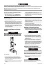
1. Install a new Throttle Valve Seat (2) by pushing it into
position in the Housing (1) with a 13/16” dowel.
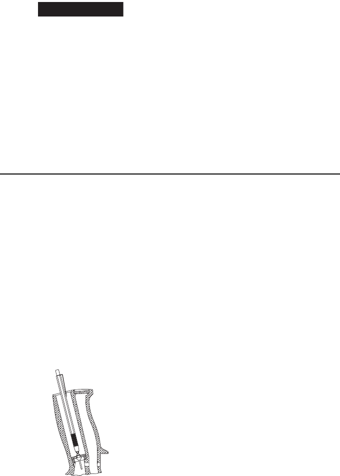
2. Insert the short end of the stem of the Throttle Valve (5)
into the jaws of an expanding-type mechanical pencil.
Allow the jaws to retract around stem to secure it.
3. Install the Throttle Valve on the Valve Seat.
See Dwg. TPD1919.
(Dwg. TPD1919)
4. As an alternate assembly procedure, drop the Throttle
Valve, long stem first, into the inlet passage. If the throttle
Valve does not sit squarely on the Throttle valve Seat,
shake the Handle until it seats.
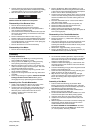
5. Install the Throttle Valve Spring (6), small end first, with
the inside diameter of the small first coil around the hub
of the Throttle Valve.
6. Coat the Inlet Bushing O-ring (9) with O-ring lubricant and
install it on the Inlet Bushing (8).
7. Screw the Inlet bushing into the Housing until snug and
tighten to 50-55 ft. lbs. (68-75 Nm) torque.
8. Wipe the stem of the Trigger Assembly (3) with light
grease and insert the stem of the Trigger into the trigger
bore in the Housing until it snaps into place on the
Throttle Valve.
Assembly of the Motor
1. Pack the Front Rotor Bearing (30) and Rear Rotor
Bearing (22) with the recommended grease. Install the
Front Rotor Bearing in the Front End Plate (29) and the ar
Rotor Bearing in the Rear End Plate (23).
2. Slide the assembled Rear End Plate and Rear Rotor
Bearing on the hub of the Rotor (25).
3. Set the assembled Rear End Plate and Rotor on a clean
surface with the spline of the Rotor pointing upward.
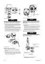
4. Insert the Vanes (26) in the vane slots on the Rotor.
5. Install the Front and Rear Cylinder Dowels (28) in the
Cylinder (27).
6. Slide the Cylinder over the Rotor and Vanes making sure
that the Rear Cylinder Dowel enters the notch in the
outside diameter of the Rear End Plate.
For Series 2925RBP1Ti and 2925RBP3Ti: Assemble
Cylinder with exhaust ports to LEFT of top dead center
(11 o’clock position). See Dwg. TPD1921.