


EN-4 04584348_ed2
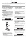
(Dwg. TPD1921)
NOTICE
If more power is needed for forward operation than for
reverse operation, install the Cylinder with exhaust ports
to the RIGHT of top dead center (1 o’clock position).
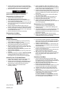
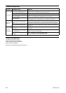
7. Install the assembled Front End Plate and Bearing over
the front, splined end of the Rotor making sure that the
front Cylinder Dowel fits into the notch in the outside
diameter of the Front End Plate.
8. Grasp the Housing with one hand and set it upside down
on its top. With the other hand, carefully guide the motor
assembly into the Housing, making sure that the side of
the motor assembly containing the Cylinder Dowels is
oriented to the top of the Housing. Install Locating Pin (24)
into Housing and End Plate. See Dwg. TPD1920-1.
(Dwg. TPD1920-1)
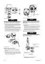
Assembly of the Reverse Valve
1. Coat a new Reverse Valve O-ring (31) with O-ring
lubricant and install it in the groove on the Reverse
Valve (32).
2. Install the Reverse Valve in the reverse valve bushing
with the slotted end trailing, making sure that the index
mark on the Reverse Valve is aligned with the index mark
on the Bushing. See Dwg. TPD1913.
(Dwg. TPD1913)
NOTICE
The Reverse Valve must be installed and indexed with
the bushing as directed in Step 2 and Dwg. TPD1913.
Failure to do so will cause improper operation of the
Reverse Valve.
3. Insert the Reverse Lever (18) through the rear of the
Backcap (16).
4. Slide the Reverse Lever Spring (20) over the shaft of the
Reverse Lever and secure the Spring and Reverse Lever
by installing the Reverse Lever Snap Ring (19) in the
groove in the shaft of the Reverse Lever. Rotate the
Reverse Lever so that it is pointing to the symbol for
FORWARD (clockwise) operation. See Dwg. TPD1913.
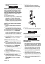
Assembly of the Impact Mechanism
NOTICE
To ensure proper Reverse Valve operation, the Reverse
Lever must stay in this position when installing the
Backcap and Reverse Valve.
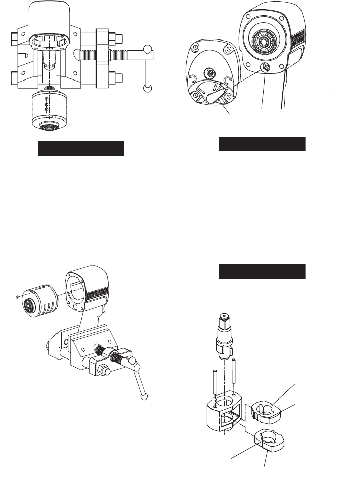
(Dwg. TPD652)
1. Coat the Hammers (35) with a light film of
Ingersoll Rand No. 170 Grease.
R
EVER
SE
LEVER IN
FO
R
W
ARD POSITION
WW
ALIGN REVERSE V
A
V
V
L
V
L
L
E
TIMIN
G
MARK WITH
M
ARK
O
N REVER
S
E
V
A
V
V
L
VE BUSHING LO-
L
L
CA
TED IN HOUSING
A
A
TOP HAMMER HALF–ROUND
NOTCH ON RIGHT
TOP HAMMER
WIDE BEVEL UP
BOTTOM HAMMER
HALF–ROUND
NOTCH ON LEFT
BOTTOM HAMMER
WIDE BEVEL DOWN