


10569408_ed1 3
WARNING
The following procedure requires the use of heat. Take
all necessary precautions to prevent burns. Carefully
heat alternate sides of Housing until it is very warm.
Using thick, heavy gloves to avoid being burned, grasp
Housing and repeat attempt to dislodge Cylinder.
8. Open a set of vise jaws wide enough to clear hub of Front End Plate
and sharply rap hub end of end plate on top of jaws to dislodge Front
Rotor Bearing.
9. Remove two Air Port Gaskets (29) and Air Port Gasket
Retainers (28) from Housing.
Disassembly of the Handle
1. Clamp Trigger Handle Assembly in leather-covered or copper-
covered vise jaws with the Straight Inlet (10) upward.
2. Using a wrench, unscrew and remove Inlet as well as Air Strainer
Screen (9) and valve Spring (8).
3. Remove Throttle Valve Assembly (6) and Valve Plunger (5) from
Handle.
4. If Trigger (3) must be removed, use an arbor press to push Trigger
Pin (4) from the Handle and slide Trigger out of slot in Handle.
Assembly
General Instructions
1. Always press on the inner ring of a ball-type bearing when installing
the bearing on a shaft.
2. Always press on the outer ring of a ball-type bearing when installing
the bearing into a bearing recess.
3. Whenever grasping a tool or part in a vise, always use leather-
covered or copper-covered vise jaws. Take extra care with threaded
members and housings.
4. Always clean every part and wipe every part with a thin film of oil
before installation.
5. Apply a film of O-ring lubricant to all O-rings before final assembly.
Assembly of the Handle
1. Position Trigger (3) in Handle (1) and using an arbor press, push
Trigger Pin (4) full length into Handle so that it captures Trigger.
2. Clamp Handle in leather-covered or copper-covered vise jaws with
air inlet opening upward.
3. Coat Throttle Valve Plunger (5) with oil and insert it, rounded end
leading, into the inlet hole in Handle.
4. Install a new Throttle Valve Seal (7) on Throttle Valve (6) and insert
assembly, Valve Seal leading, into inlet hole in Handle.
5. Encircle cone end of Air Strainer Screen (9) with large end of Throttle
Valve Spring (8) and insert both parts, Spring leading, into the inlet
hole in Handle.
6. Install Straight Inlet (10) over Strainer Screen in Handle and tighten
Inlet between 50 and 60 ft-lb (68 and 81 Nm) torque.
7. Remove Handle from vise and test Trigger. If Trigger functions
properly, place assembled Handle aside. If it does not function
properly, disassemble Handle to determine cause of problem.
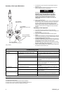
Assembly of the Motor
1. Lightly clamp Motor Housing (26) in leather-covered or copper-
covered vise jaws with handle end upward.
NOTICE
Excessive clamping pressure will distort the Motor
Housing and make motor installation extremely difficult.
Do not insert the hammer case end of the Motor
Housing more than 1” (25 mm) into the vise jaws.
2. Grease Front Rotor Bearing (25) and install it in recess of Front End
Plate.
3. Coat inside surface of Housing and outer edge of
Front End Plate (24) with a light film of oil.
4. Using a long tee hex wrench as an alignment pin, insert Front End
Plate, copper face trailing, into Motor Housing. Align dowel hole in
End Plate with dowel hole at the bottom of motor bore.
5. Lubricate and insert a new fiber Air Port Gasket Retainer (28) in one
of the air ports inside Motor Housing.
6. Install an Air Port Gasket (29) in the air port against Gasket Retainer
with flat end of Gasket away from Retainer.
7. Repeat Steps 5 and 6 to install remaining Gasket and Retainer in the
other air port.
8. Coat outside of Cylinder (21) with a light film of oil and using long tee
hex wrench as an alignment pin to align the holes in Cylinder with
holes in Front End Plate and Housing, insert Cylinder into Housing.
9. Coat inside of Cylinder and Rotor (22) with a light film of oil and insert
the splined hub of Rotor through Cylinder into Front End Plate.
10. Coat each Vane (23) with a light film of oil and insert a Vane into each
slot in the Rotor. Vanes must be installed with curved edge toward
center of Rotor. Spin the Rotor to settle Vanes in position.
11. Using long tee hex wrench to align hole in Rear End Plate (20) with
hole in Cylinder, insert the Rear End Plate, bronze face leading, into
Motor Housing against the Cylinder. End Plate is properly seated
when large trailing face of End Plate is slightly below face of Motor
Housing.
12. Grease Rear Rotor Bearing (18) and install it in recess of Rear End
Plate.
13. Remove alignment pin from assembled motor and install Cylinder
Dowel (19). The Dowel is properly seated when end of Dowel does
not protrude above End Plate.
14. Install Motor Clamp Washer(s) (16) against Rear End Plate so that
large outer edge of Washer contacts End Plate.
Assembly of the Reverse Valve
1. Inject a small amount of grease into hole in Motor Housing (26)
where Reverse Lock Plunger (30) will be installed. With grease to
hold them in position, install Reverse Lock Plunger Spring (31) and
Lock Plunger.
2. Install a new Reverse Valve Bushing Seal (14) in annular groove on
Reverse Valve (13).
3. Coat Reverse Valve with a light film of oil and install it in Motor
Housing with the side hole nearest to Seal pointed toward Rotor (22).
4. Position Reverse Lever (12) on Reverse Valve and while using a thin
blade screwdriver to depress Reverse Lock Plunger, push Lever onto
Reverse Valve.
5. Place a new Handle Gasket (17) on the Motor Housing.
6. Examine Reverse Valve Seal (11) located inside Handle and if it is
nicked, deformed or worn, remove it and install a new Seal.
7. Fill rotor cavity in Handle with recommended grease and position
Handle on the Motor Housing.
8. For 3940 and 3942 Series: Install four Handle Cap Screws (15) and
using an alternate tightening pattern, tighten Screws to between 10
and 12 ft-lb (14 and 16 Nm) torque.
For 3955 Series: Install four Handle Cap Screws (15) and using an
alternate tightening pattern, tighten Screws to between 25 and 28 ft-
lb (34 and 38 Nm) torque.
9. Move Reverse Lever through the forward and reverse positions to
make certain the Lever locks in position.
10. Turn assembly in vise jaws and clamp on Handle with rotor shaft
upward.
11. Pack Front Rotor Bearing with additional grease and rotate rotor
shaft. If shaft does not rotate smoothly, rap end of rotor shaft with a
soft hammer to set motor and try to rotate shaft again.