


4 10569408_ed1
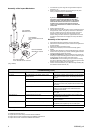
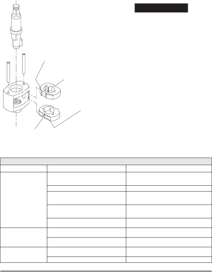
Assembly of the Impact Mechanism
(Dwg. TPD652)
1. Coat Hammers (37) with a light film of Ingersoll-Rand Impactool
Grease No. 170.
2. Replace Hammers in Hammer Frame (35) exactly as they were
when you marked them prior to disassembly.
NOTICE
If you are installing new Hammers, or want to change
the location of the existing Hammers to utilize both
impacting surfaces, slide the Hammers in the Hammer
Frame so that the half-round notch on one Hammer is
located on one side of the Frame and the half-round
notch on the other Hammer is located on the other side
of the Frame.
3. Replace Hammer Pins (36).
4. Examine base of Anvil (38) and note its contour. While looking down
through Hammer Frame, swing the top Hammer to its full extreme
one way or another until you can match the contour of the Anvil.
Enter the Anvil into the Hammer Frame and through the first
Hammer. Swing the bottom Hammer in opposite direction from the
top Hammer and maneuver Anvil slightly until it drops into bottom
Hammer.
Assembly of the Impactool
1. Set assembled hammer mechanism onto rotor shaft spline.
2. Place Hammer Case Gasket (34) over mechanism and against face
of Motor Housing.
3. Grease Anvil and top of Hammer Frame.
4. Place Hammer Case (39) over mechanism assembly against
Gasket.
5. Assemble Dead Handle (43) to Dead Handle Bracket (42). Insert two
Hammer Case Cap Screws (41). Position assembly against Hammer
Case and thread the Screws into Housing.
6. For 3940 and 3942 Series: Thread remaining two Cap Screws into
Housing and using an alternating pattern for all four fasteners, tighten
Screws between 20 and 25 ft-lb (27 and 34 Nm) torque.
For 3955 Series: Thread remaining two Cap Screws into Housing
and using an alternating pattern for all four fasteners, tighten Screws
between 35 and 40 ft-lb (47 and 54 Nm) torque.
7. Install a new Exhaust Silencer (33) in Motor Housing Assembly (26)
and install the Exhaust Deflector (32).
Related Documentation
For additional information refer to:
Air Impact Wrench Product Safety Information Manual 04580916.
Air Impact Wrench Product Information Manuals 10569382 and 80160716.
Air Impact Wrench Parts List Manuals 10569390 and 80160724.
TOP HAMMER
WIDE BEVEL UP
TOP HAMMER
HALF–ROUND NOTCH ON
RIGHT
BOTTOM HAMMER
WIDE BEVEL DOWN
BOTTOM HAMMER
HALF–ROUND NOTCH ON LEFT
Troubleshooting Guide
Trouble Probable Cause Solution
Low power Dirty Inlet Bushing or Air Strainer Screen and/or
Exhaust Silencer.
Using a clean, suitable, cleaning solution, in a well ventilated
area, clean Air Strainer Screen, Inlet Bushing and Exhaust
Silencer.
Worn or broken Vanes. Replace the complete set of Vanes.
Worn or broken Cylinder and/or scored End Plates. Examine the Cylinder and replace it if it is worn or broken or
if the bore is scored or wavy. Replace the End Plates if they
are scored.
Dirty motor parts. Disassemble tool and clean all parts with a suitable cleaning
solution, in a well-ventilated area. Reassemble tool as
instructed in this manual.
Improper positioning of the Reverse Valve. Make certain that the Reverse Valve is fully engaged to the
left or right.
Motor will not run Incorrect assembly of the motor. Disassemble the motor and replace worn or broken parts
and reassemble as instructed.
Insufficient lubricant in the impact mechanism. Remove the Hammer Case Assembly and lubricate the
impact mechanism.
Tool will not impact Broken or worn impact mechanism parts. Remove the Hammer Case and examine the impact
mechanism parts. Replace any worn or broken parts.
Impact Mechanism not assembled correctly. Refer to Assembly of the Impact Mechanism.