


DISASSEMBLY AND ASSEMBLY OF TOOLS
Disconnect air supply from tool or shut off air supply and exhaust
(drain) line of compressed air BEFORE performing maintenance
or service to tool.
Before starting to disassemble or assemble this tool (any part or
completely), be sure to read “Inspection, Maintenance and Instal-
lation” section,
To minimize the possibility of parts damage and for convenience,
the steps for disassembly or assembly listed on the following
pages are recommended.
The basic sections and instructions for removing them from the
tool are as follows:
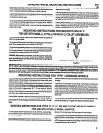
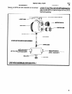
MOTOR SECTION
Place head of tool in a suitable holding device, clamping on flats of
head. Remove collet nut and collet insert. Insert a 5/32” hex type
wrench thru collet body into end of rotor to secure rotor and un-
thread and remove collet body from rotor. Remove lock nut
(37253) and remove motor assembly from housing. See page B
for complete disassembly of motor.
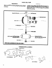
HEAD SECTION
Throttle components can be serviced without removing head sec-
tion from tool. See page 9 and 10 for complete disassembly,