MOTOR SECTION
DISASSEMBLY
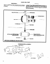
Remove motor assembly from housing as outlined on page 6.
Remove retaining nut (33694). Grasp cylinder in one hand and
tap threaded end of rotor with a soft face hammer; motor will come
apart.
ASSEMBLY
NOTE: Pack bearings with ARO 33153 grease and coat i.d. of cyl-
inder with ARO 29665 spindle oil upon assembly.
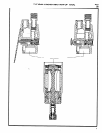
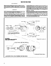
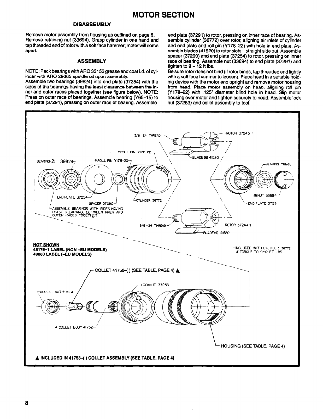
Assemble two bearings (39624) into end plate (37254) with the
sides of the bearings having the least clearance between the in-
ner and outer races placed together (see figure below). NOTE:
Press on outer race of bearings. Assemble bearing (Y65-15) to
end plate (37291), pressing on outer race of bearing. Assemble
end plate (37291) to rotor, pressing on inner race of bearing. As-
semble cylinder (36772) over rotor, aligning air inlets of cylinder
and end plate and roll pin (Y176-22) with hole in end plate. As-
semble blades (41520) to rotor slots -straight side out. Assemble
spacer (37290) and end plate (37254) to rotor, pressing on inner
race of bearing. Assemble nut (33694) to end plate (37291) and
tighten to 9 - 12 ft Ibs.
Be sure rotor does not bind (if rotor binds, tap threaded end lightly
with a soft face hammer to loosen). Place head in a suitable hold-
ing device with the motor end upright and remove motor housing
from head. Place motor assembly on head, aligning roll pin
(Y176-22) with .125” diameter blind hole in head. Slip motor
housing over motor and tighten securely to head. Assemble lock
nut (37253) and Collet assembly to tool.
TROLL
PIN Yl78-22~
3/8-24
THREA
37245-l
TROLL PIN
Yl76-
END PLATE
37254
SPACER 37290
-BLADE (6141520 /
:
EARING Y65-15
\
kND PLATE 37291
LASSEMEi..E
I\_
BEARINGS WITH SIDES HAVING
LEAST CLEARANCE BETWEEN IMUER AND
CUTER RACES TOGETqR
-\
318 -24 THREAD
i!%i%tiEL (NON -EU MODELS)
-t-INCLUDED WITH CYLINDER 36772
49999 LABEL (-EU MODELS)
$X TORQUE TO 9-12 FT LBS
/-
COLLET 41750-( ) (SEE TABLE, PAGE 4) A
I
OCKNUT 37253
COLLET NUT 41751 A
A COLLET BODY 41752
HOUSING (SEE TABLE, PAGE 4)
A INCLUDED IN 41753-( ) COLLET ASSEMBLY (SEE TABLE, PAGE 4)
8


