


DISASSEMBLY/ASSEMBLY INSTRUCTIONS
M104
13
l Never apply excessive pressure by a holding device which may
cause distortion of a part.
l Apply pressure evenly to parts which have a press fit.
l Apply even pressure to the bearing race that will be press fitted
to the mating part.
l Use correct tools and fixtures when servicing this tool.
l Don’t damage “O” rings when servicing tool.
l Use only genuine ARO replacement parts for this tool. When or-
dering, specify part number, description, tool model number and
serial number.
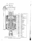
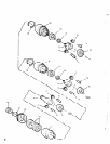
TAPPER DISASSEMBLY
-Remove stop ring (37625).
-Loosen set screw (42920) and remove clutch adjustment cap
(42125), releasing spring plate (42126). Clutch springs (42133 and
42134) con now be removed.
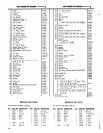
-Remove chuck nut (40490), collet (37431-2), screw (38034) and
jaw (40488).
-Remove nut (37635), spring (37632), retaining ring (42140) and
stop arm (42138).
-Remove retaining ring (44792) and gear washer (44793).
-Remove spindle (40486) with reversing sleeve (44794).
-Remove spacer (44802).
-Remove clutch sleeve (44790), clutch driver (42141), clutch plates
(42143, 42144 and 42142) and clutch disc (42145).
-Remove spring cup driver (44797) and spring (42135).
-To disassemble spindle components, remove drive pins (42599)
and press spindle (40486) out of reversing sleeve (44794).
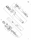
TAPPER ASSEMBLY
-Tapping units are packed with grease and only need periodic ad-
ditions to maintain proper lubrication. It is suggested that after
approximately 600 hours of operation, a small amount (1/4 to 3/4
oz. - 7 to 21 g.) of grease 33153 be added. This unit must be dis-
assembled to apply grease. An excessive amount of lubricant will
create internal frictlon and overheating.
-
-Thoroughly clean and lubricate all parts requiring lubrication. Do
not get clutch parts wet or oily.
-Assemble clutch plate (42142) on clutch sleeve (44790) with bear-
ing (42130).
-Assemble clutch disc (42145), clutch plate (42144), Clutch disc
(42145), clutch plate (42143) and clutch disc (42145) to clutch
sleeve (44790).
-Line up clutch dogs and assemble to clutch driver (42141).
-Assemble spring (42135) and spring cup driver (44797) into hous-
ing, and assemble clutch driver (42141) with clutch plates and
clutch sleeve (44790) into housing, insuring that notches in Clutch
driver align with driver pins (42127) in housing.
-Assemble spacer (44802) to housing.
-Press spindle (40486) into reversing sleeve (44794).
-Assemble three drive pins (42599) to spindle and assemble into
housing.
-Assemble gear washer (44793) to housing, securing with retain-
ing ring (44792).
-Assemble spring (37632) into spindle (40486) and secure with
nut (37635).
-Assemble jaw (40488) to spindle, securing with screw (38034).
-Assemble collet (37431-2) to spindle, securing with chuck nut
(40490).
-Assemble clutch springs (42134 and 42133), spring plate (42126),
clutch adjusting cap (42125) and stop ring (37625) to housing.
-Assemble stop arm (42138) to tapper, securing with retaining ring
(42140).
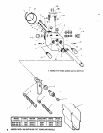
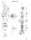
42123-1 TAPMATIC ATTACHMENT & TORQUE ARM ASS’Y
OPERATOR INSTRUCTIONS
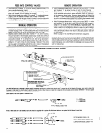
It is extremely IMPORTANT that a short arm (such as furnished) be employed with the tapping attachment to assure the best performance
of the planetary gear reversing mechanism.
Before installing the tapping attachment, thoroughly clean the machine spindle. Insert the desired tap into the tap chuck of the attachment
so the back jaws will engage the square of the tap. Tighten chuck nut first, then tighten back jaws. This will assure true running of the tap.
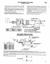
The tapping attachment incorporates a spring loaded clutch. Driving torque adjustment is made by tightening or loosening the knurled clutch
adjusting cap (42125). When the desired torque has been determined, the cap may be locked in place by tightening set screw (42920).
The proper clutch adjusting procedure, when beginning tapping operation, is to loosen adjusting cap until all graduations on housing are
visible, then tighten cap progressively until the unit will drive a sharp tap. If a clattering noise is heard during the tapping cycle, it means
that the rollers in the units drive spindle have reached a neutral position and are seeking engagement with either the driving or reversing
splines. NEVER permit this clattering to occur, as it will adversely effect the life of the attachment. The correct method of operation is to ad-
vance the machine spindle firmly to where the tap enters the hole, the tap then begins to feed itself into the work piece, follow behind with
the machine spindle until the desired depth is reached. Lead pressure is not required with this attachment.
The free axial float in the attachment will automatically allow the top to follow its own lead. A SHORT, QUICK, reaction movement of the
machine spindle will instantly reverse the top at any time. The tap will return to a right-handed rotation OS soon OS it is withdrown from the
hole. During reversal, retract the machine spindle ahead of the lead of the top but not to the point where you ore pulling against the tap
itself. The spring loaded clutch will slip when the top reaches bottom in blind hole tapping. If the clutch slips before the top reaches the
desired depth, it is evident that the tap is dull and should be replaced immediately with a sharp tap. THE CLUTCH SHOULD NOT BE TIGHTENED
FURTHER. When the clutch releases, a buzzing sound is produced - this is not detrimental to the unit.
5