


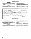
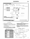
SPINDLE SECTION
DISASSEMBLY
a. Remove driver (43163) from spindle. Tap end of spindle with a
soft face hammer to loosen and remove spindle out nose end
(44605) and bearing (33237) to housing.
of housing.
b. Assemble spindle to housing and assemble driver (43163) to
spindle.
ASSEMBLY
a. Assemble felt seal (44606), wave washer (43150), bearing
(42516) -shielded side towards nose end of housing -spacer
c. Assemble “O” ring (Y325-22), screen (43641) and diffuser
(43168) to housing and assemble to tool with coupling
(43203), spacer (43164) and driver (43162).
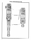
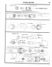
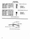
MOTOR SECTION
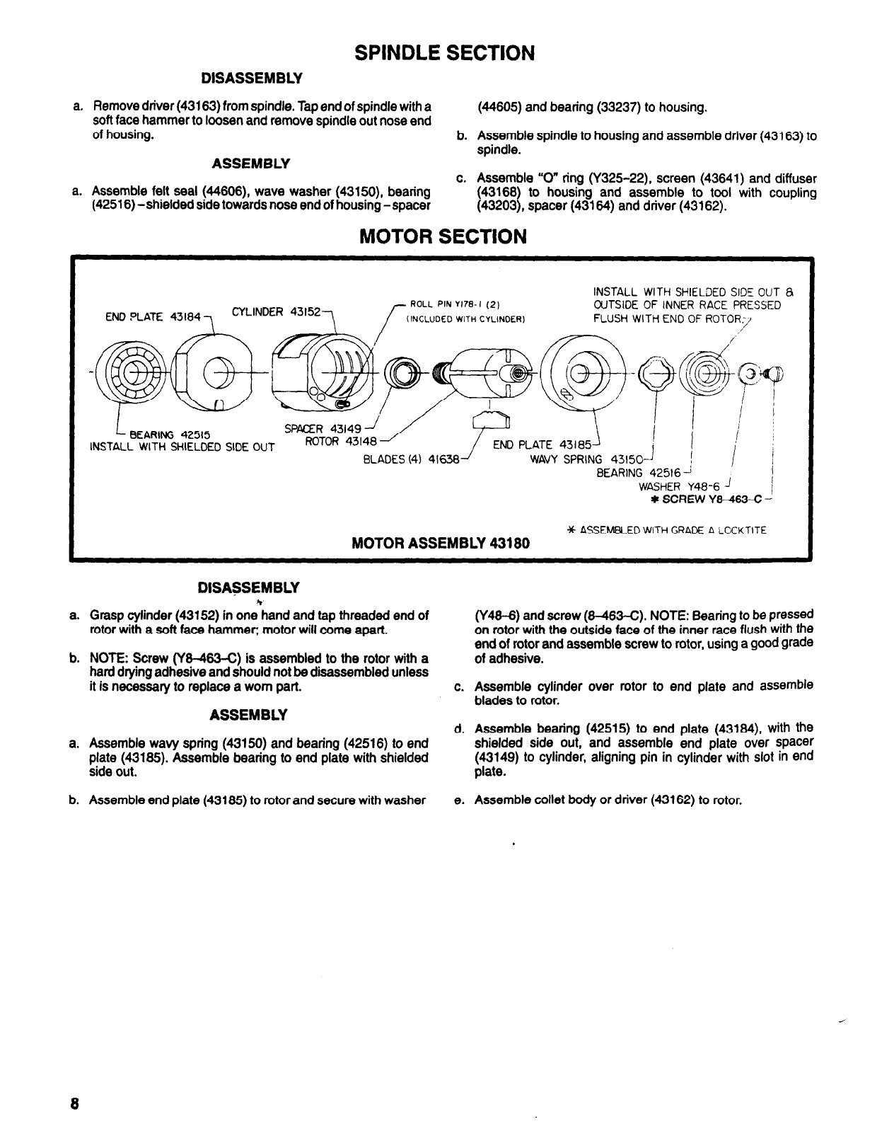
END PLATE 43184
1
CYLINDER 43152
7
INSTALL WITH SHIELDED SIDE OUT &
OUTSIDE OF INNER RACE PRESSED
FLUSH WITH END OF ROTOR
SPACER 43149
J
BEARING 42515
INSTALL WITH SHIELDED SIDE OUT
ROTOR 43148
PLATE 43185
BLADES (4) 41638-/ WAVY SPRING 43150-’
BEARING 42516
WASHER Y48-6 ’
I
* SCREW
Y8-463-C J
* ASSEMBLED WITH GRADE A LOCKTITE
MOTOR ASSEMBLY 43180
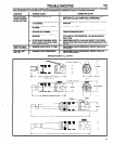
DISASSEMBLY
a. Grasp cylinder (43152) in one hand and tap threaded end of
rotor with a soft face hammer; motor will come apart.
b. NOTE: Screw (Y8-463-C) is assembled to the rotor with a
hard drying adhesive and should not be disassembled unless
it is necessary to replace a worn part.
ASSEMBLY
a. Assemble wavy spring (43150) and bearing (42516) to end
plate (43185). Assemble bearing to end plate with shielded
side out.
b. Assemble end plate (43185) to rotor and secure with washer
e. Assemble collet body or driver (43162) to rotor.
(Y48-6) and screw (8-463-C). NOTE: Bearing to be pressed
on rotor with the outside face of the inner race flush with the
end of rotor and assemble screw to rotor, using a good grade
of adhesive.
c. Assemble cylinder over rotor to end plate and assemble
blades to rotor.
d. Assemble bearing (42515) to end plate (43184), with the
shielded side out, and assemble end plate over spacer
(43149) to cylinder, aligning pin in cylinder with slot in end
plate.
8