


ROUTINE LUBRICATION REQUIREMENTS
Ml0
32
Lack of or an excessive amount of lubrication will affect the perfor-
mance and life of this tool. Use only recommended lubricants at
below time intervals:
EVERY 8 HOURS OF TOOL OPERATION
- Fill lubricator reser-
voirof recommended F.R.L. with spindle oil (29665). If an in line or
air line lubricator is not used, apply several drops of spindle oil
(29665) in air inlet.
EVERY 40 HOURS OF TOOL OPERATION
- Flush tool with a
solution of three (3) parts cleaning solvent to one (1) part spindle
oil. After flushing, apply a small amount of spindle oil in air inlet and
run tool for one minute to insure proper lubrication.
AIR SUPPLY REQUIREMENTS
For maximum operating efficiency, the following air supply specifi-
cations should be maintained to this air tool:
l
AIR PRESSURE - 90 p.s.i.g. (6.2 bar)
l
AIR FILTRATION - 50 micron
l
LUBRICATED AIR SUPPLY
l
HOSE SIZE - 3/8" (10 mm) I.D.
An ARO® model C28231-810 airline FILTER/REGULATOR/LU-
BRICATOR (F.R.L.) is recommended to maintain the above air
supply specifications.
RECOMMENDED LUBRICANTS
After disassembly is complete, all parts, except sealed or shielded
bearings, should be washed with solvent. To relubricate parts, or
for routine lubrication, use the following recommended lubricants:
Where ARO Description
Air Motor
29665
1 qt Spindle Oil
“O” Rings & Lip Seals
36460 4
oz. Stringy Lubricant
Gears and Bearings 33153 5 lb. “EP” - NLGI #1 Grease
INSPECTION, MAINTENANCE AND INSTALLATION
Disconnect air supply from the tool or shut off air supply and ex-
haust (drain) line of compressed air before performing mainte-
nance or service to the tool.
It is important that the tools be serviced and inspected at regular
intervals for maintaining safe, trouble free operation of the tool.
Be sure the tool is receiving adequate lubrication, as failure to Iu-
bricate can create hazardous operating conditions resulting from
excessive wear.
Be sure that the air supply lines and connectors are of proper size
to provide a sufficient quantity of air to the tool.
Tool maintenance and repair shall be performed by authorized,
trained, competent personnel. Tools, hose and fittings shall be re-
placed if unsuitable for safe operation and responsibility should
be assigned to be sure that all tools requiring guards or other safe-
ty devices shall be kept in legible condition. Maintenance and re-
pair records should be maintained on all tools. Frequency of
repair and the nature of the repairs can reveal unsafe application.
Scheduled maintenance by competent authorized personnel
should detect any mistreatment or abuse of the tool and worn
parts. Corrective action should be taken before returning the tool
for use.
Disassembly should be done on a clean work bench with a clean
cloth spread to prevent the loss of small parts. After disassembly
is completed, all parts should be thoroughly washed in a clean sol-
vent, blown dry with air and inspected for wear levels, abuse and
contamination. Double sealed or shielded bearings should never
be placed in solvent unless a good method of m-lubricating the
bearing is available. Open bearings may be washed but should
not be allowed to spin while being blown dry.
Upon reassembling, lubricate parts where required. Use 33153
grease, or equivalent, in bearings. Use 36460 lubricant for “O”
ring assembly. When assembling “O” rings or parts adjacent “O”
rings, care must be exercised to prevent damage to the rubber
sealing surfaces. A small amount of grease will usually hold steel
balls and other small parts in place while assembling.
Before mounting a wheel, after all tool repairs and whenever a
grinder is issued for use, the speed of the grinder shall be checked
with a tachometer to make certain that its actual speed does not
exceed its rated speed.
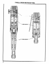
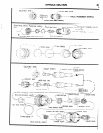
When replacement parts are necessary, consult drawing contain-
ing the part for identification.
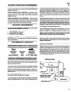
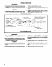
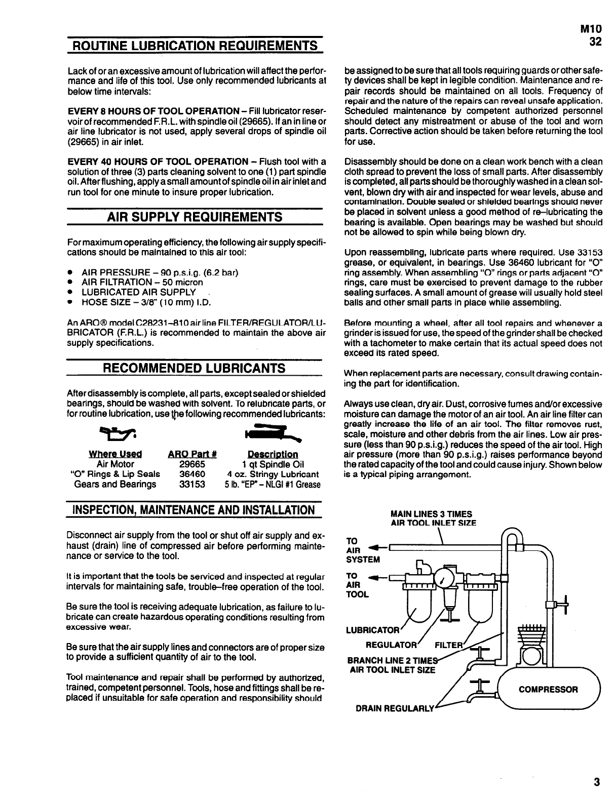
Always use clean, dry air. Dust, corrosive fumes and/or excessive
moisture can damage the motor of an air tool. An air line filter can
greatly increase the life of an air tool. The filter removes rust,
scale, moisture and other debris from the air lines. Low air pres-
sure (less than 90 p.s.i.g.) reduces the speed of the air tool. High
air pressure (more than 90 p.s.i.g.) raises performance beyond
the rated capacity of the tool and could cause injury. Shown below
is a typical piping arrangement.
MAIN LINES 3 TIMES
AIR TOOL INLET SIZE
\ -
TO
AIR -
SYSTEM
E -
TOOL
LUBRICATOR
REGULATOR
BRANCH UNE 2 TIME
AIR TOOL INLET SIZE
COMPRESSOR
DRAIN REGULARLY
3