


DISASSEMBLY AND ASSEMBLY OF TOOLS
Ml0
Disconnect air supply from tool or shut off air supply and exhaust
(drain) line of compressed air BEFORE performing maintenance
or service to tool.
Before starting to disassemble or assemble this tool (any part or
completely), be sure to read “Inspection, Maintenance and Instal-
lation” section.
To minimize the possibility of parts damage and for convenience,
the steps for disassembly or assembly listed on the following
pages are recommended.
The basic sections and instructions for removing them from the
tool are as follows:
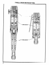
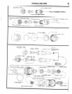
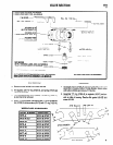
SPINDLE SECTION
Models with short spindle: Remove collet guard (43897) with dif-
fuser (43893), “O” ring (Y325-22) and spring (43894). Remove
collet nut, collet and lock screw (43898).
Models with extension spindle: Remove spindle housing (44601)
and exhaust diffuser (43168) with screen (43641). Remove
spacer (43164) and drive coupling (43203).
MOTOR SECTION
Remove spindle section, grasp rotor and pull motor assembly
from housing. Remove collet body or driver (43162). NOTE: Insert
a screwdriver thru the end of the collet body or driver to hold
spindle or rotor.
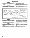
VALVE SECTION
Throttle valve and components may be removed from housing
without disassembling any other part of the tool.
5